
Deployment Guide


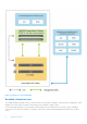
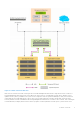
Table Of Contents
- Microsoft HCI Solutions from Dell Technologies Deployment Guide
- Contents
- Introduction
- Solution Overview
- Solution Deployment
- Introduction to solution deployment
- Deployment prerequisites
- Predeployment configuration
- Operating system deployment
- Installing roles and features
- Verifying firmware and software compliance with the support matrix
- Updating out-of-box drivers
- Changing the hostname
- Configuring host networking
- Joining cluster nodes to an Active Directory domain
- Deploying and configuring a host cluster
- Best practices and recommendations
- Recommended next steps
- Deployment services
- References
- Appendix A: Persistent Memory for Windows Server HCI

If you are using an RODC at the remote site, connectivity to the central management infrastructure with a writeable domain
controller is mandatory during deployment of the Azure Stack HCI cluster.
NOTE: Dell Technologies does not support expansion of a two-node cluster to a larger cluster size. A three-node cluster
provides fault-tolerance only for simultaneous failure of a single node and a single drive. If the deployment requires future
expansion and better fault tolerance, consider starting with a four-node cluster at a minimum.
NOTE: For recommended server and network switch placement in the racks, port mapping on the top-of-rack (ToR)
and OOB switches, and details about configuring the ToR and OOB switches, see Network Integration and Host Network
Configuration Options.
This deployment guide provides instructions and PowerShell commands for manually deploying an Azure Stack HCI cluster. For
information about configuring host networking and creating an Azure Stack HCI cluster by using System Center Virtual Machine
Manager (VMM), see Preparing and Using SCVMM for Azure Stack HCI Network and Cluster Configuration.
Stretched cluster infrastructure
The Azure Stack HCI operating system added a new feature to support disaster recovery between two sites using Azure Stack
HCI clusters. With Storage Replica as its foundation, stretched clusters support both synchronous and asynchronous replication
of data between two sites. The replication direction (uni- or bi-directional) can be configured for either an active/passive or
active/active stretched cluster configuration.
NOTE: Stretched clustering infrastructure is supported only with the Azure Stack HCI operating system. For more
information, see the Dell EMC Integrated System for Microsoft Azure Stack HCI: Stretched Cluster Deployment Reference
Architecture Guide.
Solution integration and network connectivity
Each of the variants in Microsoft HCI Solutions from Dell Technologies supports a specific type of network connectivity. The
type of network connectivity determines the solution integration requirements.
● For information about all possible topologies within both fully converged and nonconverged solution integration, including
with switchless storage networking and host operating system network configuration, see Network Integration and Host
Network Configuration Options.
● For switchless storage networking, carry out the server cabling according to the instructions detailed in Cabling Instructions.
● For sample switch configurations for these network connectivity options, see Sample Network Switch Configuration Files.
Fully converged network connectivity
In the fully converged network configuration, both storage and management/VM traffic use the same set of network adapters.
The adapters are configured with Switch Embedded Teaming (SET). In this network configuration, when using RoCE, you must
configure data center bridging (DCB).
The following table shows when to configure DCB based on the chosen network card and switch topology:
Table 1. DCB configuration based on network card and switch topology
Network card on node Switch topology
Fully converged
a
Nonconverged
Mellanox (RoCE) DCB (required) DCB (required) for storage network
adapters only
b
QLogic (iWARP) DCB (not required) No DCB
a.
For simplicity, all converged sample switch configurations have DCB configured for both Mellanox and QLogic cards.
However, for QLogic (iWARP), except for high-performance configurations such as all-NVMe, DCB is not required.
b.
Updated guidance on Mellanox nonconverged topology.
NOTE: DCB should be enabled only on storage network adapters.
10 Solution Overview