
Release Notes

PCIe cooling strategy in PowerEdge servers
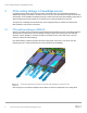
7 PCIe Card Cooling with Dell EMC PowerEdge Servers
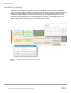
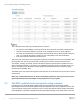
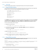
iDRAC web UI snapshot for PCIe Airflow Settings
The UI illustrated in the above figure enables the user to observe:
• The maximum LFM capability of each slot within the server when the max LFM is at full fan speeds
• How each slot is being managed—by airflow control, temperature control, or target LFM value
• The minimum LFM delivered to any third-party card slots allows users to decide whether to keep this
LFM, or to customize its settings at a higher or lower value based on the card specifications
• PCIe inlet temperature distribution across the slots
This UI overview of the system PCIe cooling plan provides key information such as max LFM capability. With
this information, the user can reconfigure their controller layout to achieve reduced system fan power
consumption, ensuring, for example, that the card with the highest LFM requirement is installed in the slot
with the highest LFM capacity. This feature is only available for third-party cards. For Dell EMC cards, LFM
value is not displayed since Dell EMC’s thermal algorithm automatically determines the optimal cooling
requirements for Dell EMC cards.
The default system fan response for third-party PCIe cards can only be turned off one slot at a time to prevent
cooling issues.
NOTE: It is recommended that you do not turn off the default system fan response unless you have a
good understanding of the PCIe adapter cooling requirements in your system.
2.2 Dell EMC-qualified cards and optimal cooling response
PowerEdge servers identify Dell EMC-qualified cards through proprietary communications. All Dell
EMC-designed cards and many EMC-qualified cards have temperature monitoring capabilities that are used
to provide optimal cooling through closed-loop control. If system level thermal controls identify cards without
these capabilities, it prescribes a predetermined fan speed response based on the airflow needs of the card.