Dell™ Precision™ T3500 Service Manual Working on Your Computer Adding and Replacing Parts Specifications Diagnostics About Your System Board System Setup Notes, Cautions, and Warnings NOTE: A NOTE indicates important information that helps you make better use of your computer. CAUTION: A CAUTION indicates potential damage to hardware or loss of data if instructions are not followed. WARNING: A WARNING indicates a potential for property damage, personal injury, or death.
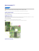
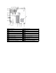
About Your System Board Dell Precision™ T3500 Service Manual Password Enable Jumper NVRAM Reset Jumper System Board Schematic WARNING: Before working inside your computer, read the safety information that shipped with your computer. For additional safety best practices information, see the Regulatory Compliance Homepage at www.dell.com/regulatory_compliance. Your computer's system board offers two jumpers—a password enable jumper and a RTCRST (Real Time Clock Reset) jumper.
1 PCI Card Slot (Slot 6) 2 PCI Card Slot (Slot 5) 3 PCIe x16 (Slot 4) 4 PCIe x4 (Slot 3) 5 PCIe x16 (Slot 2) 6 PCIe x4 (Slot 1) 7 Audio Front Panel (FP_AUDIO) 8 Internal USB (USB_1) 9 LPC_DEBUG 10 Processor Connector 11 CPU Power Connector (POWER_CPU) 12 Front Bezel Fan (FAN_Front) 13 Front Cage Fan (FAN_CCAG) 14 Memory Module (RAM) Connectors (DIMM_1-6) 15 Jumpers (PSWD & RTCRTS) 16 Battery Socket (CMOS Battery) 17 Internal USB Socket (for Flexbay Card Reader) 18 Main Pow
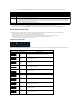
System Setup Dell Precision™ T3500 Service Manual POST Keystrokes Boot Menu Entering System Setup System Setup Navigation Keystrokes POST Keystrokes Your computer has several keystroke options available during the POST process at the Dell™ Logo screen. Keystroke Function Description < F2> Enter System Setup Use System Setup to make changes to the user-definable settings.
Select field to change Cancel a modification Reset defaults or Load Defaults menu option NOTE: Depending on your computer and any installed devices, the items listed in this section may or may not appear.
Diagnostics Dell Precision™ T3500 Service Manual Dell Diagnostics Power Button Light Codes Diagnostic Light Codes Beep Codes Dell Diagnostics When to Use the Dell Diagnostics It is recommended that you print these procedures before you begin. NOTE: The Dell Diagnostics software works only on Dell computers. NOTE: The Drivers and Utilities disc is optional and may not ship with your computer.
3. If you run a test from the Custom Test or Symptom Tree option, click the applicable tab described in the following table for more information. Tab Function Results Displays the results of the test and any error conditions encountered. Errors Displays error conditions encountered, error codes, and the problem description. Help Describes the test and may indicate requirements for running the test. Configuration Displays your hardware configuration for the selected device.
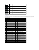
1 2 3 4 - On Off On On Possible system board resource and/or system board hardware failure. 1 2 3 4 - On On Off Off Possible system resource configuration error. 1 2 3 4 - On On On Off Other failure. 1 2 3 4 - On On On On End of POST - Hand off to boot. 1 2 3 4 - Off Off Off Off The system is in a normal operating condition after POST. Beep Codes When errors occur during a boot routine that cannot be reported on the monitor, the computer may emit a beep code that identifies the problem.
Adding and Replacing Parts Dell Precision™ T3500 Service Manual Cover I/O Panel Front Bezel Power Supply Hard Drive Drives Bezel Floppy Drive Optical Drive Memory Card Reader Memory Memory Shroud Expansion Card Battery Chassis Intrusion Switch Video Card Fan Assembly Heat Sink and Processor Systemboard I/O Data Cable
Specifications Dell Precision™ T3500 Service Manual Drives Processors Connectors System Information Controls and Lights Memory Power Video Physical Audio Environmental Expansion Bus NOTE: Offerings may vary by region. For more information regarding the configuration of your Tablet-PC, click Start (or Start in Windows XP)® Help and Support, and then select the option to view information about your Tablet-PC.
Note: The platform can accommodate third and fourth 3.5-inch hard drives in the flex bay or the optical drive bay. (4 HDD support is limited to SATA only & tower orientation only, SAS is limited to 3 HDD) Available devices 3.5-inch SATA hard drives SATA DVD, SATA CD-RW/DVD Combo, SATA DVD+/-RW, SATA BD Combo (Blu-Ray playback only), SATA Blu-ray R/W One 3.
Drive activity light Green light . A blinking green light indicates the computer is reading data from or writing data to the SATA hard drive or CD/DVD. Network link light Green light . Solid green indicates a connection to an active network Off (no light) . System is not connected to a network Back of the computer: Link integrity light (on integrated network adapter) Network activity light (on integrated network adapter) Green . A good connection at 10Mbs exists between the network and the computer.
Battery Dell Precision™ T3500 Service Manual WARNING: Before working inside your computer, read the safety information that shipped with your computer. For additional safety best practices information, see the Regulatory Compliance Homepage at www.dell.com/regulatory_compliance. Removing the Battery 1. 2. 3. Follow the procedures in Before Working Inside Your Computer. Remove the computer cover. Lift the hard drive tray.
Cover Dell Precision™ T3500 Service Manual WARNING: Before working inside your computer, read the safety information that shipped with your computer. For additional safety best practices information, see the Regulatory Compliance Homepage at www.dell.com/regulatory_compliance. Removing the Cover 1. Follow the procedures in Before Working Inside Your Computer. 2. Pull the cover release latch toward the back of the computer.
3. Pivot the cover away from the computer and then remove the cover.
Drives Bezel Dell Precision™ T3500 Service Manual WARNING: Before working inside your computer, read the safety information that shipped with your computer. For additional safety best practices information, see the Regulatory Compliance Homepage at www.dell.com/regulatory_compliance. Removing Drives Bezel 1. 2. 3. Follow the procedures in Before Working Inside Your Computer. Remove the computer cover. Remove the front bezel. 4. Push the sliding plate lever down to release the drives bezel.
5. Tilt the drives bezel away from the front of the computer. 6. Remove the drives bezel from the computer.
Front Bezel Dell Precision™ T3500 Service Manual WARNING: Before working inside your computer, read the safety information that shipped with your computer. For additional safety best practices information, see the Regulatory Compliance Homepage at www.dell.com/regulatory_compliance. Removing the Front Bezel 1. 2. Follow the procedures in Before Working Inside Your Computer. Remove the computer cover. 4. While pressing the release tab down (1) slide the bezel toward the top of the computer (2).
5. Remove the bezel from the front of the computer.
Front Fan Assembly Dell Precision™ T3500 Service Manual WARNING: Before working inside your computer, read the safety information that shipped with your computer. For additional safety best practices information, see the Regulatory Compliance Homepage at www.dell.com/regulatory_compliance. Removing the Front Fan Assembly 1. 2. 3. Follow the procedures in Before Working Inside Your Computer. Remove the computer cover. Lift the hard drive tray: a.
4. Remove the memory module shroud. 5. Disconnect the two fan cables from the system board.
6. Remove the screw securing the front fan assembly to the computer. 7. Lift the front fan assembly straight up and remove it from the computer.
Floppy Drive Dell Precision™ T3500 Service Manual WARNING: Before working inside your computer, read the safety information that shipped with your computer. For additional safety best practices information, see the Regulatory Compliance Homepage at www.dell.com/regulatory_compliance. Removing the Floppy Drive 1. 2. 3. 4. 5. 6. 7. Follow the procedures in Before Working Inside Your Computer. Remove the computer cover. Remove the front bezel. Remove the drives bezel.
Hard Drives Dell Precision™ T3500 Service Manual WARNING: Before working inside your computer, read the safety information that shipped with your computer. For additional safety best practices information, see the Regulatory Compliance Homepage at www.dell.com/regulatory_compliance. Removing the Hard Drives 1. 2. Follow the procedures in Before Working Inside Your Computer. Remove the computer cover. 3. Disconnect the power cable and data cable from the first hard drive.
4. Lift the two release tabs on the first hard drive. 5. Squeeze the two release tabs toward each other and hold.
6. Tilt the hard drive towards away from the release tabs. 7. Remove the first hard drive from the computer at an angle. . 8. Repeat the process with the second hard drive.
Hard Drive Tray Dell Precision™ T3500 Service Manual WARNING: Before working inside your computer, read the safety information that shipped with your computer. For additional safety best practices information, see the Regulatory Compliance Homepage at www.dell.com/regulatory_compliance. Removing the Hard Drive Tray 1. 2. 3. 4. Follow the procedures in Before Working Inside Your Computer. Remove the computer cover. Remove the hard drives from the hard drive tray.
7. Remove the three screws securing the hard drive tray to the computer. 8. Remove the hard drive tray from the computer.
Chassis Intrusion Switch Dell Precision™ T3500 Service Manual WARNING: Before working inside your computer, read the safety information that shipped with your computer. For additional safety best practices information, see the Regulatory Compliance Homepage at www.dell.com/regulatory_compliance. Removing the Chassis Intrusion Switch 1. 2. 3. 4. 5. 6. Follow the procedures in Before Working Inside Your Computer. Remove the computer cover.
I/O Data Cable Dell Precision™ T3500 Service Manual WARNING: Before working inside your computer, read the safety information that shipped with your computer. For additional safety best practices information, see the Regulatory Compliance Homepage at www.dell.com/regulatory_compliance. Removing the I/O Data Cable 1. 2. 3. 4. 5. 6. Follow the procedures in Before Working Inside Your Computer. Remove the computer cover. Raise the hard drive tray. Remove the memory module shroud.
I/O Panel Dell Precision™ T3500 Service Manual WARNING: Before working inside your computer, read the safety information that shipped with your computer. For additional safety best practices information, see the Regulatory Compliance Homepage at www.dell.com/regulatory_compliance. Removing the I/O Panel 1. 2. 3. 4. 5. Follow the procedures in Before Working Inside Your Computer. Remove the computer cover. Raise the hard drive tray. Remove the memory module shroud. Remove the front fan assembly. 6.
7. Disconnect the USB cable from the I/O panel. 8. Remove the screw that secures the I/O panel to the computer.
9. Remove the I/O panel from the computer.
Memory Dell Precision™ T3500 Service Manual Supported Memory Configurations Removing and Replacing Memory Modules Your computer uses 1066 MHz or 1333Mhz DDR3 unbuffered SDRAM memory. DDR3 SDRAM, or double-data-rate three synchronous dynamic random access memory, is a random access memory technology. It is a part of the SDRAM family of technologies, which is one of many DRAM (dynamic random access memory) implementations, and is an evolutionary improvement over its predecessor, DDR2 SDRAM.
4. Remove the memory module shroud. 5. Using your thumbs, gently push down on the memory module retention clips at either end of the module to release the module from the system board connector. 6. Lift the memory module straight up and out of the computer.
7. Repeat the process for any remaining memory modules.
Floppy Drive Dell Precision™ T3500 Service Manual WARNING: Before working inside your computer, read the safety information that shipped with your computer. For additional safety best practices information, see the Regulatory Compliance Homepage at www.dell.com/regulatory_compliance. Removing the Memory Card Reader 1. 2. 3. 4. 5. 6. 7. Follow the procedures in Before Working Inside Your Computer. Remove the computer cover. Remove the front bezel. Remove the drives bezel.
Memory Shroud Dell Precision™ T3500 Service Manual WARNING: Before working inside your computer, read the safety information that shipped with your computer. For additional safety best practices information, see the Regulatory Compliance Homepage at www.dell.com/regulatory_compliance. Removing the Memory Shroud 1. 2. 3. Follow the procedures in Before Working Inside Your Computer. Remove the computer cover. Raise the hard drive tray: a.
4. Lift the memory shroud straight up and out of the system.
Optical Drive Dell Precision™ T3500 Service Manual WARNING: Before working inside your computer, read the safety information that shipped with your computer. For additional safety best practices information, see the Regulatory Compliance Homepage at www.dell.com/regulatory_compliance. Removing the Optical Drive 1. 2. 3. 4. Follow the procedures in Before Working Inside Your Computer. Remove the computer cover. Remove the front bezel. Remove the drives bezel. 5.
6. Push the sliding-plate lever down to release the optical drive. 7. Remove the optical drive from the computer.
Heat Sink and Processor Dell Precision™ T3500 Service Manual WARNING: Before working inside your computer, read the safety information that shipped with your computer. For additional safety best practices information, see the Regulatory Compliance Homepage at www.dell.com/regulatory_compliance. Removing the Heat Sink and Processor 1. 2. 3. Follow the procedures in Before Working Inside Your Computer. Remove the computer cover. Lift the hard drive tray: a.
4. Remove the memory module shroud. 5. Loosen the four captive screws on the heatsink.
6. Lift the heat sink straight up and remove from the computer. 7. Open the processor cover by sliding the release lever from under the center cover latch on the socket. 8. Lift the processor cover on its hinge to release the processor.
9. Carefully lift the processor straight up and remove it from the system.
Power Supply Dell Precision™ T3500 Service Manual WARNING: Before working inside your computer, read the safety information that shipped with your computer. For additional safety best practices information, see the Regulatory Compliance Homepage at www.dell.com/regulatory_compliance. Removing the Power Supply 1. 2. Follow the procedures in Before Working Inside Your Computer. Remove the computer cover. 3. Tilt the expansion card retention arm towards the edge of the computer. 4.
5. Remove the four screws that secure the hard drive at the back of the computer. 6. Push down on and hold the power supply release tab. 7. Slide the power supply towards the interior of the computer until it clears the metal frame.
8. Lift the power supply straight up and remove from the computer.
System Board Dell Precision™ T3500 Service Manual WARNING: Before working inside your computer, read the safety information that shipped with your computer. For additional safety best practices information, see the Regulatory Compliance Homepage at www.dell.com/regulatory_compliance. Removing the System Board 1. 2. 3. Follow the procedures in Before Working Inside Your Computer. Remove the computer cover. Lift the hard drive tray: a. Push and hold the blue release tab toward the bottom of the computer.
4. 5. 6. 7. 8. 9. 10. Remove Remove Remove Remove Remove Remove the memory module shroud. the front fan assembly. the expansion card if applicable. the video card. the heat sink and processor. any memory modules. Disconnect the power supply data cable.
11. Disconnect the system board power cable. 12. Disconnect the optical and hard drive data cables.
13. Disconnect the I/O data cable. 14. Remove the twelve screws that secure the system board to the computer chassis.
15. Slide the system board towards the front of the chassis. 16. Lift the system board up at an angle towards the edge of the chassis.
17. Remove the system board from the computer chassis.
Video Card Dell Precision™ T3500 Service Manual WARNING: Before working inside your computer, read the safety information that shipped with your computer. For additional safety best practices information, see the Regulatory Compliance Homepage at www.dell.com/regulatory_compliance. Removing the Video Card 1. 2. Follow the procedures in Before Working Inside Your Computer. Remove the computer cover. 3. Lift the expansion card retention assembly arm away from the chassis.
4. Squeeze the expansion card retention assembly release tabs together and hold. 5. Continue tilting the expansion card retention assembly towards the outside of the computer.
6. Pull the blue release tab on the system board away from the video card. NOTE: The expansion card has been removed to increase visibility to the following procedure. 7. Lift the video card straight up and remove the card from the computer.
Expansion Card Dell Precision™ T3500 Service Manual WARNING: Before working inside your computer, read the safety information that shipped with your computer. For additional safety best practices information, see the Regulatory Compliance Homepage at www.dell.com/regulatory_compliance. Removing the Expansion Card 1. 2. Follow the procedures in Before Working Inside Your Computer. Remove the computer cover. 3. Lift the expansion card retention assembly arm away from the chassis.
4. Squeeze the expansion card retention assembly release tabs together and hold. 5. Continue tilting the expansion card retention towards the outside of the computer.
6. Disconnect the USB cable from the expansion card. 7. Lift the expansion card straight up and remove from the computer.
Working on Your Computer Dell™ Precision™ T3500 Service Manual Before Working Inside Your Computer Recommended Tools Turning Off Your Computer After Working Inside Your Computer Before Working Inside Your Computer Use the following safety guidelines to help protect your computer from potential damage and to help to ensure your personal safety.
The computer turns off after the operating system shutdown process is complete. 2. Ensure that the computer and all attached devices are turned off. If your computer and attached devices did not automatically turn off when you shut down your operating system, press and hold the power button for about 6 seconds to turn them off. After Working Inside Your Computer After you complete any replacement procedure, ensure you connect any external devices, cards, and cables before turning on your computer. 1. 2.