
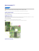
Personal Computer User Manual


3. If you run a test from the Custom Test or Symptom Tree option, click the applicable tab described in the following table for more information.
4. When the tests are completed, if you are running the Dell Diagnostics from the Drivers and Utilities disc, remove the disc.
5. Close the test screen to return to the Main Menu screen. To exit the Dell Diagnostics and restart the computer, close the Main Menu screen.
Power Button Light Codes
The power LED located in the power button on the front of the computer illuminates and blinks or remains solid to indicate five different states:
l No light—System is in the off state (S5, or mechanical (AC power not applied) OFF).
l Solid Amber—System fault, but Power Supply is good—normal operating state (S0 ).
l Blinking Amber—System fault error condition including Power Supply (only +5VSB working), Vreg failure, missing or bad CPU.
l Blinking Green—System is in power saving states S1, S3 or S4. (Blink rate is 1Hz). No fault/error condition.
l Solid Green—System is fully functional and is in S0 (ON) state.
Diagnostic Light Codes
Four (4) single color lights are incorporated on the front control panel to serve as a diagnostic aid for troubleshooting systems exhibiting No Post/No Video
symptoms. The lights do not report runtime errors.
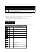
Tab
Function
Results
Displays the results of the test and any error conditions encountered.
Errors
Displays error conditions encountered, error codes, and the problem description.
Help
Describes the test and may indicate requirements for running the test.
Configuration
Displays your hardware configuration for the selected device.
The Dell Diagnostics obtains configuration information for all devices from system setup, memory, and various internal tests, and it displays
the information in the device list in the left pane of the screen. The device list may not display the names of all the components installed on
your computer or all devices attached to your computer.
Parameters
Allows you to customize the test by changing the test settings.
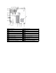
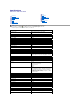
Diagnostic LED Patterns
LED pattern (1234)
LED Description
State description
1 - Off
2 - Off
3 - Off
4 - On
BIOS checksum failure detected; system is in recovery mode.
1 - Off
2 - Off
3 - On
4 - Off
Possible processor failure.
1 - Off
2 - Off
3 - On
4 - On
Memory failure.
1 - Off
2 - On
3 - Off
4 - Off
Possible expansion card failure.
1 - Off
2 - On
3 - Off
4 - On
Possible video failure.
1 - Off
2 - On
3 - On
4 - Off
Diskette drive or hard drive failure.
1 - Off
2 - On
3 - On
4 - On
Possible USB failure.
1 - On
2 - Off
3 - Off
4 - Off
No memory modules detected.
1 - On
2 - Off
3 - Off
4 - On
System board failure.
1 - On
2 - Off
3 - On
4 - Off
Memory configuration error.