
Installation and Service Manual


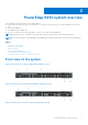

Table Of Contents
- Dell EMC PowerEdge R250 Installation and Service Manual
- Contents
- About this document
- PowerEdge R250 system overview
- Initial system setup and configuration
- Minimum to POST and system management configuration validation
- Installing and removing system components
- Safety instructions
- Before working inside your system
- After working inside your system
- Recommended tools
- Optional front bezel
- System cover
- Optional optical drive
- Air shroud
- Cooling fans
- Intrusion switch
- Drive backplane
- Drives
- Cable routing
- System memory
- Processor and heat sink
- Expansion cards and expansion card risers
- Optional IDSDM module
- MicroSD card
- Optional BOSS S1 card
- PERC
- System battery
- Optional internal USB card
- Power supply unit
- System board
- Trusted Platform Module
- Control panel
- Jumpers and connectors
- System diagnostics and indicator codes
- Getting help
- Documentation resources

PowerEdge R250 system overview
The PowerEdge R250 system is a 1U server that supports:
● One Intel Xeon E-2300 series processor with up to 8 + 2 execution cores per processor or Intel Pentium processor with 2
cores
●
Four DDR4 DIMM slots
● One cabled AC power supply unit
● Up to four 3.5-inch SAS/SATA hot-plug drives or up to four 3.5-inch SATA cabled drives.
NOTE: All instances of SAS, SATA drives are referred to as drives in this document, unless specified otherwise.
NOTE: For more information, see the Dell EMC PowerEdge R250 Technical Specifications on the product documentation
page.
Topics:
• Front view of the system
• Rear view of the system
• Inside the system
• System information label
• Rail sizing and rack compatibility matrix
• Locating the Express Service Code and Service Tag
Front view of the system
Figure 1. Front view of 4 x 3.5-inch cabled SAS/SATA drive system
Figure 2. Front view of 4 x 3.5-inch SAS/SATA hot-swap drive system
Figure 3. Front view of 2 x 3.5-inch cabled SAS/SATA drive system
2
PowerEdge R250 system overview 7