Dell EMC VMware Cloud Foundation 4.0 for PowerEdge MX7000 Deployment Guide May 2020 Rev.
Notes, cautions, and warnings NOTE: A NOTE indicates important information that helps you make better use of your product. CAUTION: A CAUTION indicates either potential damage to hardware or loss of data and tells you how to avoid the problem. WARNING: A WARNING indicates a potential for property damage, personal injury, or death. © 2019 2020 Dell Inc. or its subsidiaries. All rights reserved. Dell, EMC, and other trademarks are trademarks of Dell Inc. or its subsidiaries.
Contents 1 Audience and scope...................................................................................................................... 6 2 Overview..................................................................................................................................... 7 3 Pre-deployment requirements.......................................................................................................9 Management host...................................................................
Domain Name System...................................................................................................................................................28 Network Time Protocol.................................................................................................................................................28 Simple Mail Transfer Protocol mail relay (optional)...................................................................................................
Prerequisites.........................................................................................................................................................................47 Installation of ESXi...............................................................................................................................................................47 Connect to iDRAC and boot installation media.....................................................................................................
1 Audience and scope This deployment guide includes step-by-step instructions for deployment of VMware Cloud Foundation on Dell EMC PowerEdge MX7000 modular platform. Any deviation from the listed configurations may negatively impact functionality. This deployment guide makes certain assumptions about the prerequisite knowledge of the deployment personnel.
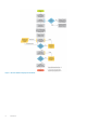
2 Overview Deployment of VMware Cloud Foundation on the PowerEdge MX7000 modular platform provides a hyperconverged infrastructure solution incorporating best-in-class hardware from Dell EMC with core VMware products including vSphere, vSAN, NSX, vRealize Log Insight, and SDDC Manager. Virtualization of compute, storage, and networking is delivered in a single package with VMware Cloud Foundation on PowerEdge MX7000.
Figure 1.
3 Pre-deployment requirements Management host The deployment of VMware Cloud Foundation is executed by a Cloud Builder VM that is deployed using an Open Virtualization Appliance (OVA). The virtual machine must be deployed on an ESXi host or cluster that is not a part of the Cloud Foundation cluster. If the management network is a private network ensure that the Cloud Builder VM and the Cloud Foundation management hosts have access to the same DNS and NTP services.
Domain Name Service Domain Name Service (DNS) is required to provide both forward and reverse name resolution. The IP addresses of name servers, search domains, and hostnames of all the Cloud Foundation VMs must be inserted into the cloud builder deployment parameter sheet. Forward and reverse DNS entries of any hostname that are indicated in the parameter sheet should be tested and retested for both forward and reverse lookups.
4 Validated components VMware no longer maintains a VMware Compatibility Guide for Cloud Foundation. Since vSAN is an underlying requirement of Cloud Foundation, any hardware specified as a vSAN Ready Node is approved for Cloud Foundation. Topics: • • • Hardware components Software and firmware Software Hardware components The following hardware components were used in the validation of this solution.
controllers, and network interface cards. For more information on other components, see https://www.dell.com/ support. Software This document is written for Cloud Foundation 4.0 running on VMware ESXi 7.0. The required build and version of VMware ESXi is specified by the version of Cloud Foundation to be installed. It is critical that the versions of both the Cloud Foundation and VMware ESXi correspond.
5 Hardware overview This section provides additional information about the hardware platform used in the development of this deployment guide.
Figure 3. PowerEdge MX7000 chassis—front view Back view of the PowerEdge MX7000 chassis The back of the PowerEdge MX7000 chassis provides access to network and storage fabrics, management modules, fans, and power connections.
Figure 5. Logical view of the PowerEdge MX7000 chassis Dell EMC PowerEdge MX740c compute sled Dell EMC PowerEdge MX740c is a two-socket, full-height, single-width compute sled that offers high performance and scalability. It is ideal for dense virtualization environments and can serve as a foundation for collaborative workloads.
Figure 6. Dell EMC PowerEdge MX740c compute sled Dell EMC PowerEdge MX5016s storage sled The PowerEdge MX5016s storage sled delivers scale-out, shared storage within the PowerEdge MX architecture. The PowerEdge MX5016s sled provides customizable 12 GB/s direct-attached SAS storage with up to 16 SAS hard drives or SSDs. Both the PowerEdge MX740c and the PowerEdge MX840c compute sleds can share drives with the PowerEdge MX5016s sled using the PowerEdge MX5000s SAS module.
Figure 7. Dell EMC PowerEdge MX5016s storage sled Dell EMC PowerEdge MX9002m management module The Dell EMC PowerEdge MX9002m management module controls the overall chassis power, cooling, and hosts the OpenManage Enterprise-Modular (OME-M) console. Two external 1G-BaseT Ethernet ports are provided to enable management connectivity and to connect more PowerEdge MX7000 chassis into a single logical chassis. The PowerEdge MX7000 chassis supports two PowerEdge MX9002m management modules for redundancy.
Dell EMC Networking MX9116n Fabric Switching Engine The Dell EMC Networking MX9116n Fabric Switching Engine (FSE) is a scalable, high-performance, low latency 25 GbE switch purposebuilt for the PowerEdge MX platform. The MX9116n FSE provides enhanced capabilities and cost-effectiveness for enterprise, midmarket, Tier 2 cloud, and Network Functions Virtualization (NFV) service providers with demanding compute and storage traffic environments.
NOTE: The MX7116n FEM cannot act as a stand-alone switch and must be connected to the MX9116n FSE to function. Dell EMC Networking MX5108n Ethernet switch The Dell EMC Networking MX5108n Ethernet switch is targeted at small PowerEdge MX7000 deployments of one or two chassis. Although not a scalable switch, it still provides high-performance and low latency with a non-blocking switching architecture.
6 Physical layout There are multiple configurations of Cloud Foundation on PowerEdge MX7000 chassis that are described in this document. The Cloud Foundation software addresses the host servers using their IP Address. Deploying compute sleds across multiple PowerEdge MX7000 chassis has no impact on the software as long as the networking is configured properly on the Networking IO modules and the switches to which the PowerEdge MX7000 chassis connects.
Figure 14. Single PowerEdge MX7000 with MX5016s storage sled Option 3—two PowerEdge MX7000 enclosures • • • Two Dell EMC PowerEdge MX7000 enclosures Four Dell EMC PowerEdge MX740c compute sleds Four Dell EMC Networking MX5108n Ethernet switches Figure 15.
Figure 16.
Figure 17. Two PowerEdge MX7000 enclosures using Fabric Switching Engine Cabling PowerEdge MX5016s storage sleds are internally cabled and the PowerEdge MX5000s SAS IOM has no impact on external cabling. Cabling for a dual PowerEdge MX7000 enclosure configuration using Fabric Switching Engines The following figures show the external cabling for a multiple PowerEdge MX7000 enclosure configuration when the MX9116n Fabric Switching Engines and MX7116n Fabric Expansion Modules are used.
Figure 18.
Figure 19.
Figure 20.
7 Cloud Foundation and SDDC design considerations VMware Cloud Foundation relies on a set of key infrastructure services to be made available externally. You must configure these external services before you begin deployment. NOTE: This section is universal for Cloud Foundation deployments regardless of hardware platform. The content in this section is also available in the VMware Cloud Foundation Planning and Preparation Guide, and is included here for reference.
NOTE: If you plan to deploy vRealize Automation, Active Directory services must be available. For more information on AD configuration, see the vRealize Automation documentation. Dynamic Host Configuration Protocol Cloud Foundation uses Dynamic Host Configuration Protocol (DHCP) to automatically configure each VM kernel port of an ESXi host that is used as a TEP with an IPv4 address. One DHCP scope must be defined and made available for this purpose.
Network pools Cloud Foundation uses a construct that is called a network pool to automatically configure VM kernel ports for vSAN, NFS, and vMotion. Cloud Foundation uses an Internet Protocol Address Management (IPAM) solution to automate the IP configuration of VM kernel ports for vMotion, vSAN, and NFS (depending on the storage type being used). When a server is added to the inventory of Cloud Foundation, it goes through a process called host commissioning.
Host names and IP addresses for external services External services such as Active Directory (AD) and NTP must be accessible and resolvable by IP Address and Fully Qualified Domain Name (FQDN). Acquire the hostnames and IP addresses for AD and NTP before deploying Cloud Foundation. Allocate hostnames and IP addresses to the following components: • • • • NTP AD DNS Certificate Authority (CA) The following table provides sample information for the external services.
Table 5. Configuration for the virtual infrastructure layer(continued) Workload Domain Hostname DNS Zone IP Address Description vcfmgmthost02 osevcf17.local 100.71.101.172 Management Host 2 vcfmgmthost03 osevcf17.local 100.71.101.173 Management Host 3 vcfmgmthost04 osevcf17.local 100.71.101.
8 Networking requirements This section covers the networking requirements from both the Cloud Foundation software perspective and from a networking hardware connectivity perspective. This section also briefly describes the configuration options for configuring networks on a Dell EMC PowerEdge MX7000 chassis. The actual networking configuration procedures are described in the later sections.
The advantage of using the manual configuration method is that every aspect of the switch configuration is available. The switch startupconfiguration reflects every change that is made by the network administrator but this method is slower to deploy and more prone to human error. The advantage of SmartFabric is in the time it takes to deploy a configuration. With a relatively small number of configuration steps, a fabric and profile that can be assigned to the compute sleds are created.
Network connectivity When deploying Dell EMC Networking MX5108n switch modules, the switches are installed in Fabric A of the PowerEdge MX7000 enclosure. Each modular switch has eight internal ports with one port being connected to each compute sled. Two modules provide a redundant (A1 and A2) connection to each of the PowerEdge MX740c compute sleds. The connection between the compute sleds and the MX modular switches do not use any kind of link aggregation protocol.
9 Manual switch configuration This section describes the configuration of the MX9116n FSEs (Fabric Switching Engines) switches. Each PowerEdge MX7000 has one MX9116n and one MX7116n in the A fabric. The MX9116n in chassis 1 should be placed in the A1 slot and the MX9116n in chassis 2 should be placed in the A2 slot. This distributes the fabric's switching engines across both chassis. In the event of a loss of one of the MX9116n, only one half of the fabric is impacted.
no shutdown mtu 9216 NOTE: All these VLANs are created on both Top of Rack switches. NSX Switch Specific VLANs These VLANs are switch-specific and not to be created on both switches. On the first switch, create VLAN 2711 and on the second switch, create VLAN 2712. On switch one: interface vlan2711 description 2711-NSX no shutdown mtu 9216 On switch two: interface vlan2712 description 2712-NSX no shutdown mtu 9216 NOTE: These VLANs are created on different Top of Rack switches.
MX9116-A1(conf-vlt-10)# backup destination 100.71.242.220 MX9116-A1(conf-vlt-10)# exit Verify VLT settings Verify the VLT settings by running the following command: MX9116-A1# show vlt 10 Domain ID Unit ID Role Version Local System MAC address Role priority VLT MAC address IP address Delay-Restore timer Peer-Routing Peer-Routing-Timeout timer VLTi Link Status port-channel1000 : : : : : : : : : : : 10 2 secondary 2.
Here are the port channels that are created on switch one: MX9116-A1# show running-configuration interface port-channel 1 ! interface port-channel1 description "Uplink to DataCenter" no shutdown switchport mode trunk switchport trunk allowed vlan 96,1711-1713,1715 mtu 9216 vlt-port-channel 1 MX9116-A1# show running-configuration interface port-channel 11 ! interface port-channel11 description NSX_Uplink_1 no shutdown switchport mode trunk switchport trunk allowed vlan 2711,1714 mtu 9216 MX9116-A1# show port
On switch one: MX9116-A2(config)# MX9116-A2(config)# interface range ethernet 1/1/1-1/1/16 MX9116-A2(conf-range-eth1/1/1-1/1/16)# switchport mode trunk MX9116-A2(conf-range-eth1/1/1-1/1/16)# switchport trunk allowed vlan 96,1711-1715,2711 MX9116-A2(conf-range-eth1/1/1-1/1/16)# mtu 9216 MX9116-A2(conf-range-eth1/1/1-1/1/16)# no shutdown MX9116-A2(conf-range-eth1/1/1-1/1/16)# exit MX9116-A2(config)# On switch two: MX9116-A2(config)# MX9116-A2(config)# interface range ethernet 1/1/1-1/1/16 MX9116-A2(conf-range
10 SmartFabric network configuration The PowerEdge MX9002m management module hosts the OpenManage Enterprise Modular (OME-M) console. Creation and deployment of SmartFabric topologies is facilitated using the OME-Modular console in conjunction with the MX9116n switch operating system. SmartFabric is a web-based mechanism to create a reusable networking template that can be applied to a PowerEdge MX7000 chassis, the IO modules (switches) and the compute sleds.
Steps 1. After the PowerEdge MX9002m modules have been cabled together, log in to the OME-Modular web interface of the chassis that will be the lead chassis of the new chassis group. 2. From the Chassis Overview menu, click Configure, and then select Create Chassis Group. 3. Enter the group name and group description. NOTE: The group name must be one word without any spaces. 4. Select chassis onboarding permissions that propagate to each chassis that is added to the group, and then click Next.
Figure 24. VLAN configuration Create SmartFabric Creation of the SmartFabric depends on the IOM selected and the number of PowerEdge MX7000 chassis to be installed. The devices eligible for SmartFabric deployment are: • • • MX5108n Ethernet switch MX9116n Fabric Switching Engine MX7116n Fabric Expansion Module When deploying the MX5108n switch, create chassis groups for improved management but the IOMs in each chassis function independently of the IOMs in other chassis.
Figure 25. Default Fabric Expander port configuration To reconfigure the port configuration, follow the steps below: 1. 2. 3. 4. Select port-group 1/1/6 Click on Configure Breakout Set the Breakout Type to HardwareDefault Click Finish and wait for the port to be reconfigured Repeat this process on port-group 1/1/6 but, now set the Breakout Type to 2X100GE. The PORT CONFIGURATION must be returned to HardwareDefault before it can be changed to a new configuration.
8. From the Switch-B list, select Slot-IOM-A2. 9. Click Next. 10. On the Summary page, verify the proposed configuration, and then click Finish. The fabric displays a health error which is resolved in the next section by adding uplinks to your fabric. Configure uplinks About this task The newly created fabric requires uplinks to connect to the rest of the network. These uplinks are created as a single logical link to the upstream network using the same Virtual Link Trunking (VLT).
NOTE: By default, SmartFabric does not configure the jumbo MTU (frame size) on switch ports. To configure jumbo frames, set the MTU (frame size) using the following procedure: Steps 1. 2. 3. 4. 5. 6. 7. From the Devices menu, click I/O Modules. Select the IO Module. From the IOM banner menu, click Hardware. Click Port Information. Select ports Ethernet 1/1/1-Ethernet 1/1/16 and the uplink port channels. Click Configure MTU and set MTU to 9216. Click Finish.
Steps 1. In the Deploy pane, select the MX740c with Intel mezzanine server template and then click Edit Network. 2. In the Edit Network window, perform the following steps: a. Optionally, from the Identity Pool list, select Ethernet ID Pool. b. From the Untagged Network list, select the VLAN previously created to be the untagged VLAN for both ports. c. From the Tagged Network list, select all the tagged VLANs for both ports. 3. Click Finish. Results The server template is associated with the VLAN network.
11 Deploy ESXi to cluster nodes Only perform the steps listed in this section if the compute sleds were not pre-installed with ESXi 7.0. If the compute sleds have been preinstalled with ESXi 7 jump ahead to Configure ESXi settings—using DCUI. Below are the steps to install VMware ESXi on each of the PowerEdge MX740c hosts that are part of the management cluster. This guide covers the steps to install VMware ESXi remotely using iDRAC Virtual Console with Virtual Media.
6. 7. 8. 9. The mapping screen for the virtual media is displayed on the Virtual Media menu. In the Map CD/DVD section, click Choose File. Browse and select the required Dell EMC customized ESXi image (ISO image) file. Click Map Device and then click Close. 10. 11. 12. 13. From the Virtual Console menu, click Boot, and then click Virtual CD/DVD/ISO. Click Yes. From the Power menu, click Power on System. If the system is not turned on, click Power on System.
Configure ESXi settings—using DCUI About this task The Direct Console User Interface (DCUI) is a menu-based interface that is accessed from the host console and used to configure ESXi running on vSphere hosts. Steps 1. 2. 3. 4. After the server reboots and fully loads ESXi, press F2 to log in to the DCUI. Enter the credentials that were created during the ESXi installation, and then press Enter. From the System Customization menu, select Configure Management Network.
Configure ESXi settings using web interface Prerequisites Before configuring ESXi settings using web interface, you must configure the ESXi settings using DCUI. For more information, see Configure ESXi settings—using DCUI. Steps 1. Using a web browser, go to the ESXi host-level management web interface at https:///ui. 2. Enter the credentials that were created during the ESXi installation, and then click Log in. 3. In the Navigator pane, click Networking.
Figure 31. ESXi web interface—Edit time configuration page 11. In the Manage pane, select the Services tab. The resulting page is as shown in the following figure: Figure 32. ESXi settings web interface—Manage pane 12. Right-click on the ntpd service and set the policy to Start and stop with the host. Next steps Once the policy is set, start the ntpd service. If the ntpd service is already running, restart the service.
12 Cloud Builder and SDDC deployment The primary software installation tool for Cloud Foundation 4.x is Cloud Builder. It is delivered as a virtual appliance in the standard OVA format. This section describes the steps to deploy the OVA. The Cloud Builder VM is a temporary tool to facilitate deployment of Cloud Foundation. It can be discarded after the deployment.
Figure 33. OVF customize template page 11. Review the Ready to Complete final configuration page, and then click Finish. 12. In the Recent Tasks pane, check the OVA deployment status. When the OVA deployment is complete start the Cloud Builder VM.. Check Time Synchronization After the Cloud Builder VM is started, it takes some time to for all the services to start and for time synchronization to complete.
13 VCF Deployment using Cloud Builder In the previous section, you deployed the Cloud Builder virtual appliance. In this section, the software within the virtual machine is used to validate the target environment and deploy the entire Cloud Foundation stack. NOTE: Before proceeding with the Cloud Builder validation process, take a snapshot of your Cloud Builder VM.
Figure 34. Cloud Builder web interface 3. 4. 5. 6. Log in using the credentials that you specified during OVA deployment. Click Check All to review the checklist of pre-bring-up steps and confirm that all the steps that are completed, and then click Next. Review the EULA, and if you agree, click Agree to End User License Agreement, and then click Next. If you have not obtained and completed the Cloud Foundation Information Spreadsheet, click Download Deployment Parameter Sheet.
Management Workload tab License keys are required for the following items: • • • • • ESXi hosts vSAN vCenter NSX-T SDDC Manager Appliance Users and Groups tab In the Users and Groups tab, you can set the passwords for your initial Cloud Foundation components. CAUTION: Do not make a mistake on this page because if any of the passwords do not meet the indicated specifications, you must redeploy your Cloud Builder VM, unless you elected to create a snapshot after you created your VM.
4. 5. 6. 7. 8. 9. 10. 11. 12. 13. 14. 15. 16. 17. 18. Log in using the credentials that you specified during OVA deployment. Review the EULA, and if you agree, click Agree to End User License Agreement, and then click Next. Select VMware Cloud Foundation. Be sure not to select VMware Cloud Foundation on VxRAIL.
Figure 36. Configure Cloud Builder validation NOTE: Validation may take 15 minutes or more. However, if there are issues such as the DNS server being down or if you provided a wrong IP address, validation may take longer. NOTE: On the Validation Report page, you can access the information about previous validation attempts. Each validation attempt is tracked with an entry that is designated by the date and time of execution. 3.
5. Confirm deployment of vCenter, vSAN, NSX, and vRealize Log Insight. NOTE: Hostnames and IP addresses are in the Cloud Foundation Deployment Parameters spreadsheet. The Cloud Builder VM can now be discarded.
14 Post-install validation Cloud Foundation Cluster Verification After installing Cloud Foundation, perform the steps in the following sections to verify that the components are installed and available. SDDC Manager Log in to SDDC Manager using a web browser at: https://. The SSO user ID is administrator@vsphere.local and the password is the one you specified during installation. NOTE: Use the domain vsphere.local.
Figure 39. vCenter dashboard NSX Manager Log into the NSX Manager through a web browser using the Admin credentials set in your parameter sheet. Figure 40. NSX dashboard VMware Cloud Foundation installation complete Cloud Foundation has been successfully deployed and is ready for use.