
Users Guide

The advantage of using the manual configuration method is that every aspect of the switch configuration is available. The switch startup-
configuration reflects every change that is made by the network administrator but this method is slower to deploy and more prone to
human error.
The advantage of SmartFabric is in the time it takes to deploy a configuration. With a relatively small number of configuration steps, a
fabric and profile that can be assigned to the compute sleds are created. When a change is made to the fabric or profile, it can be easily
pushed out to the switches and compute sleds in the PowerEdge MX7000 chassis. The startup-config and running-config
commands do not reflect the actual configuration of the chassis switches.
Review the sections in both Manual switch configuration and SmartFabric network configuration before choosing a path.
Networking and NSX-T
Cloud Foundation version 4.0 has made a change to NSX-T from NSX, also seen as NSX-V in Cloud Foundation 3.9. The move to NSX-T
is a drive to change the physical and logical networking architecture. NSX-T introduces the concept of an Edge Node Cluster. An Edge
Node Cluster is a resilient cluster of NSX-T edge nodes that are used to connect to upstream networks. All NSX traffic leaving the cluster
passes through these edge nodes and the edge nodes rely on physical NICs.
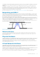
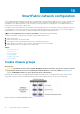
Each member of an Edge Node Cluster contains identical configurations of physical NICs so that the NSX network constructs can fail over
if there is a node failure. This diagram shows a conceptual view of the different uplinks from the top of rack switches to the spine. The
MLAG is a VLT port channel that includes connections from both top of rack switches to multiple devices in the spine layer. The two NSX-
T LAG connections are standard LACP link aggregations which connect the NSX-T edge nodes back to the spine layer.
The connections that are shown are for conceptual purposes only and are not accurate to any specific model of switch. In the case of a
MX7000 modular deployment, the MX9116n IOMs are the Top or Rack or leaf switches.
Figure 21. Top of Rack to Spine
Network Interfaces
To meet NSX-T requirements, additional NICs have to be provisioned to the Edge Nodes. Extra NICs in an MX environment can be
deployed through physical hardware or by virtualizing a physical NIC into multiple partitions that would be treated as unique network
devices at the hypervisor level.
Physical Hardware
Installing physical hardware to provide additional network interfaces in an MX7000 environment requires the installation of devices into the
B fabric of the MX7000 chassis. More MX9116n IOMs would be installed into slots B1 and B2 on the rear of the chassis. Extra network
mezzanine cards would be installed into the B connector of each of MX740c compute sleds to interface with the B fabric IOMs.
Installing dedicated hardware provides better throughput, lower latency, and simplified monitoring of network performance and metrics.
However, additional hardware can be costly.
Virtual Network Interfaces
A single A fabric network mezzanine card supports two physical ports. Each of these physical ports can be subdivided into as many as four
unique partitions using NPAR. The result is, eight network interfaces that are divided between fabrics A1 and A2. These NPAR NIC
partitions can be configured to support storage tasks and networking tasks.
Using NPAR to partition the fabric network interfaces is easy to configure and cost effective. However, the full bandwidth of the network
interface is shared across the multiple partitions resulting in less bandwidth capacity than physical hardware.
For this example, NPAR is used to divide each of the A fabric NICs into two partitions. The resulting NPAR NICs appear as two discrete
NICs. They are on each side of the A fabric (A1 and A2) thus, providing each of the management domain hosts with four NICs.
Networking requirements
33