
Users Guide

Network connectivity
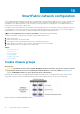
When deploying Dell EMC Networking MX5108n switch modules, the switches are installed in Fabric A of the PowerEdge MX7000
enclosure. Each modular switch has eight internal ports with one port being connected to each compute sled. Two modules provide a
redundant (A1 and A2) connection to each of the PowerEdge MX740c compute sleds. The connection between the compute sleds and
the MX modular switches do not use any kind of link aggregation protocol. The connections are separate network connections that are
managed by the Cloud Foundation stack. Due to the limited ports available for uplink the MX5108n should not be used where NSX-T edge
node capabilities are desired.
Deploying Dell EMC Networking MX9116n Fabric Switching Engines and Dell EMC Networking MX7116n Fabric Expansion Modules is a
different process. The FSEs are installed into the A1 fabric of the first chassis and the A2 fabric of the second chassis. The FEMs are
distributed across both PowerEdge MX7000 chassis in the remaining A fabric slots. The FEMs connect back to the FSEs using a double
data rate, 200 Gbps cable. The connection between the compute sleds and the MX modular switches do not use any kind of link
aggregation protocol. Additional PowerEdge MX7000 chassis (up to 8 more) can be added and require only the MX7116n FEMs in the A1
and A2 fabric slots. The additional ports available for uplink make the MX9116n an excellent choice for the deployment of NSX-T edge
nodes. Since NSX-T is now a part of Cloud Foundation 4.0 we will place the emphasis of this document on the MX9116n Scalable Fabric
Architecture.
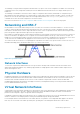
The connections from the modular switches to the external network are implemented using Virtual Link Trunking (VLT) link aggregation.
VLT allows you to create a single LACP-managed link aggregation from the two modular switches to an LACP-managed aggregation in
the external network. Use the link aggregation only on the link between the modular switches and the customer network.
VLAN and subnets for networking configuration
The following table shows the VLAN and networking data that are used for the Cloud Foundation deployment. In our example, private
addresses are used for Management, vSAN, vMotion, and VXLAN networks. However, this is not mandatory.
Table 7. VLAN and networking data used for the Cloud Foundation deployment
Name VLAN ID Subnet Mask
Default Gateway
Management 1711 172.17.11.0 255.255.255.0 172.17.11.253
vSAN 1712 172.17.12.0 255.255.255.0 172.17.12.253
vMotion 1713 172.17.13.0 255.255.255.0 172.17.13.253
VXLAN 1714 172.17.14.0 255.255.255.0 172.17.14.253
Uplink1 2711 172.27.11.0 255.255.255.0 172.27.11.1
Uplink2 2712 172.27.12.0 255.255.255.0 172.27.12.1
MTU Settings
Configuring jumbo frames is a best practice for both vMotion and vSAN networks, both of which are core components of Cloud
Foundation. All the switch ports on the modular switches and up to the aggregation switches used to connect multiple PowerEdge
MX7000 enclosures together must be configured for jumbo frames. It is also recommended to configure jumbo frames on the VXLAN
network. The validation phase run as part of the Cloud Foundation installation process tests end-to-end connectivity of all specified
devices, but fails if the jumbo frames are not correctly configured.
34
Networking requirements