Dell Vostro15–3565 Owner's Manual Regulatory Model: P47F Regulatory Type: P47F006 August 2020 Rev.
Notes, cautions, and warnings NOTE: A NOTE indicates important information that helps you make better use of your computer. CAUTION: A CAUTION indicates either potential damage to hardware or loss of data and tells you how to avoid the problem. WARNING: A WARNING indicates a potential for property damage, personal injury, or death. © 2016 2020 Dell Inc. or its subsidiaries. All rights reserved. Dell, EMC, and other trademarks are trademarks of Dell Inc. or its subsidiaries.
Contents Chapter 1: Working on your computer........................................................................................... 6 Safety instructions.............................................................................................................................................................. 6 Before working inside your computer.............................................................................................................................6 Turning off your computer.......
Installing the system board............................................................................................................................................. 27 Removing the power connector.................................................................................................................................... 28 Installing the power connector......................................................................................................................................
Camera features................................................................................................................................................................ 46 Identifying the camera in Device Manager on Windows 10...............................................................................46 Identifying the camera in Device Manager on Windows 7................................................................................ 46 Starting the camera.........................................
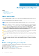
1 Working on your computer Topics: • • • • Safety instructions Before working inside your computer Turning off your computer After working inside your computer Safety instructions Use the following safety guidelines to help protect your computer from potential damage and to help to ensure your personal safety. Unless otherwise noted, each procedure included in this document assumes that the following conditions exist: ● You have read the safety information that shipped with your computer.
CAUTION: To disconnect a network cable, first unplug the cable from your computer and then unplug the cable from the network device. 5. Disconnect all network cables from the computer. 6. Disconnect your computer and all attached devices from their electrical outlets. 7. Close the display and turn the computer upside-down on a flat work surface. NOTE: To avoid damaging the system board, you must remove the main battery before you service the computer. 8. Remove the main battery. 9.
CAUTION: To avoid damage to the computer, use only the battery designed for this particular Dell computer. Do not use batteries designed for other Dell computers. 1. Connect any external devices, such as a port replicator or media base, and replace any cards, such as an ExpressCard. 2. Connect any telephone or network cables to your computer. CAUTION: To connect a network cable, first plug the cable into the network device and then plug it into the computer. 3. Replace the battery. 4.
2 Chassis view Topics: • • • • • Front open view Front closed view Rear view Right view Left view Front open view 1. Touchpad 3. Camera status light 5. Power button 2. Camera 4. Microphone 6. Keyboard Front closed view 1.
Rear view 1. Battery 2. Service Tag label Right view 1. Headset connector 3. USB 2.0 connector 5. Security cable slot 2. USB 2.0 connector 4. Optical drive Left view 1. Power connector 10 Chassis view 2.
3. VGA connector 5. Memory card reader 4. USB 3.
3 Removing and installing components This section provides detailed information on how to remove or install the components from your computer.
Recommended tools The procedures in this document require the following tools: ● ● ● ● Small flat blade screwdriver Phillips #0 screwdriver Phillips #1 screwdriver Small plastic scribe Removing the battery 1. Follow the procedure in Before working inside your computer. 2. To remove the battery: a. Slide the release latch to unlock the battery [1]. b. Remove the battery from the computer [2]. Installing the battery 1. Insert the battery into the slot and press it until it clicks into place. 2.
Removing the optical drive bracket 1. Follow the procedure in Before working inside your computer. 2. Remove the: a. battery b. optical drive 3. To remove the optical drive from bracket: a. Remove the screw that secures the optical drive bracket [1]. b. Remove the optical drive bracket from the optical drive [2]. Installing the optical drive bracket 1. Install the optical drive bracket. 2. Tighten the screw to secure the optical drive bracket. 3. Install the: a.
b. battery 4. Follow the procedure in After working inside your computer. Installing the optical drive 1. Insert the optical drive into the slot until it clicks into place. 2. Tighten the screw to secure the optical drive to the computer. 3. Install the battery. 4. Follow the procedure in After working inside your computer. Removing the keyboard 1. Follow the procedure in Before working inside your computer. 2. Remove the battery. 3. To remove the keyboard: a.
4. To remove the keyboard cable: a. Disconnect the keyboard cable from the system board [1]. b. Lift the keyboard cable to remove it from the computer [2]. Installing the keyboard 1. Connect the keyboard cable to the connector on the system board. 2. Slide the keyboard into the retention slots. 3. Press along the top edges to lock the keyboard in place. 4. Install the battery. 5. Follow the procedure in After working inside your computer. Removing the base cover 1.
4. To remove the base cover: a. Remove the screws that secure the base cover to the computer [1]. b. Pry the edges of base cover and lift it to remove it from computer [2]. Installing the base cover 1. Align the base cover with the screw holders on the computer. 2. Press the edges of the cover until it clicks into place. 3. Tighten the screws to secure the base cover to the computer. 4. Turn the computer over. 5. Open the computer and connect the optical drive connector to the system board. 6.
Removing the hard drive assembly 1. Follow the procedure in Before working inside your computer. 2. Remove the: a. b. c. d. battery optical drive keyboard base cover 3. To remove the hard drive assembly: a. Disconnect the hard drive cable from the connector on the system board [1, 2]. b. Remove the screws that secure the hard drive assembly to the computer [3]. c. Lift the hard drive assembly away from the computer [4]. Removing the hard drive from the hard drive bracket 1.
Installing the hard drive into the hard drive bracket 1. Align the screw holders and insert the hard drive into the hard drive bracket. 2. Tighten the screws to secure the hard drive to the hard drive bracket. 3. Connect the hard drive cable connector to the hard drive. 4. Install the: a. b. c. d. e. hard drive assembly base cover keyboard optical drive battery 5. Follow the procedure in After working inside your computer Installing the hard drive assembly 1.
b. Remove the memory module from the system board [2]. Installing the memory module 1. Insert the memory module into the memory socket. 2. Press the memory module until the clips secure the memory module. 3. Install the: a. b. c. d. base cover keyboard optical drive battery 4. Follow the procedures in After working inside your computer. Removing the coin cell battery 1. Follow the procedure in Before working inside your computer. 2. Remove the: a. b. c. d. battery optical drive keyboard base cover 3.
Installing the coin cell battery 1. Insert the coin cell battery into the battery slot. 2. Press the battery until it clicks into place. 3. Install the: a. b. c. d. base cover keyboard optical drive battery 4. Follow the procedures in After working inside your computer. Removing the WLAN card 1. Follow the procedure in Before working inside your computer. 2. Remove the: a. b. c. d. battery optical drive keyboard base cover 3. To remove the WLAN card: a.
Installing the WLAN card 1. Insert the WLAN card into the slot on the computer. 2. Tighten the screw to secure the WLAN card to the computer. 3. Connect the WLAN cables to the connectors on the WLAN card. 4. Install the: a. b. c. d. base cover keyboard optical drive battery 5. Follow the procedure in After working inside your computer. Removing the Input Output board 1. Follow the procedure in Before working inside your computer. 2. Remove the: a. b. c. d. battery optical drive keyboard base cover 3.
Installing the Input Output board 1. Connect the input/output (I/O board) cable to the I/O board. 2. Replace the black adhesive tape to secure the i/o board cable. 3. Turn the I/O board over and align it with the screw holder on the computer. 4. Insert the I/O board into the computer. 5. Tighten the screw to secure the I/O board to the computer. 6. Install the: a. b. c. d. base cover keyboard optical drive battery 7. Follow the procedure in After working inside your computer. Removing the speakers 1.
Installing the speakers 1. Insert the tabs on the speakers into the slots on the computer. 2. Route the speaker cable through the routing channel on the computer. 3. Connect the speaker cable to the system board. 4. Install the: a. b. c. d. base cover keyboard optical drive battery 5. Follow the procedure in After working inside your computer Removing the heat sink assembly 1. Follow the procedure in Before working inside your computer. 2. Remove the: a. b. c. d.
Installing the heat sink assembly 1. Align the screws on the heat sink with the screw holders on the system board. 2. Install the heat sink assembly and tighten the captive screws to secure it to the system board. 3. Connect the system fan cable to the system board. 4. Install the: a. b. c. d. base cover keyboard optical drive battery 5. Follow the procedures in After working inside your computer. Removing the system board 1. Follow the procedure in Before working inside your computer. 2. Remove the: a.
4. Turn the computer over and unroute the WLAN cable [1]. 5. Remove the screw and lift the hinge that secures the system board to the computer [2,3]. 6. Remove the screw that secures the system board to the computer [1] and lift the system board [2].
7. Turn the system board over. 8. To remove the system board: a. b. c. d. Remove the white adhesive tape [1]. Unlock the tab and disconnect the eDP cable [2, 3]. Disconnect the power cable [4]. Remove the system board from the computer. Installing the system board 1. Connect power cable and eDP cable. 2. Replace the white adhesive tape. 3. Turn the system board over. 4. Align the system board with the screw holders on the computer. 5. Tighten the screws to secure the system board to the computer. 6.
a. b. c. d. e. f. g. h. i. WLAN card I/O board connector memory module heat sink coin cell battery base cover optical drive keyboard battery 9. Follow the procedure in After working inside your computer. Removing the power connector 1. Follow the procedure in Before working inside your computer. 2. Remove the: a. b. c. d. e. f. g. h. i. j. k. l. battery optical drive keyboard base cover hard drive assembly optical drive WLAN card i/o board memory module coin cell battery heat sink system board 3.
3. Secure the power connector to the computer by using the screw. 4. Install the: a. b. c. d. e. f. g. h. i. j. system board WLAN card I/O board memory module heat sink coin cell battery base cover optical drive battery keyboard 5. Follow the procedure in After working inside your computer. Removing the display assembly 1. Follow the procedure in Before working inside your computer. 2. Remove the: a. b. c. d. e. f. g. h. i. j. k. l. m.
Installing the display assembly 1. Align the display assembly with the chassis. 2. Route the WLAN and display assembly cables through the cable securing tabs. 3. Tighten the display hinges screws to secure the display assembly. 4. Install the: a. b. c. d. e. f. g. h. i. j. k. coin cell battery system board power connector keyboard WLAN card I/O board memory module heat sink base cover optical drive battery 5. Follow the procedure in After working inside your computer. Removing the display bezel 1.
m. power connector n. display assembly 3. To disconnect the display bezel: a. By using a plastic scribe, release the tabs on the edges to release the display bezel from the display assembly [1]. b. Remove the display bezel display assembly [2]. Installing the display bezel 1. Place the display bezel on the display assembly. 2. Press the display bezel until it clicks onto the display assembly. 3. Install the: a. b. c. d. e. f. g. h. i. j. k. l.
j. k. l. m. n. o. coin cell battery heat sink system board power connector display assembly display bezel 3. To remove the camera: a. Remove the tape that secures the camera cable [1]. b. Disconnect the camera cable from the camera [2]. c. Remove the camera from the display assembly [3]. Installing the camera 1. Install the camera into the slot on the display assembly. 2. Connect the camera cable. 3. Install the: a. b. c. d. e. f. g. h. i. j. k. l. m.
a. b. c. d. e. f. g. h. i. j. k. l. m. n. o. p. battery optical drive keyboard base cover hard drive assembly optical drive WLAN card I/O board memory module coin cell battery heat sink system board power connector display assembly display bezel camera 3. To remove the display panel: a. Remove the screws that secure the display panel to the display assembly [1]. b. Lift the display panel to access the cables underneath [2]. 4. To disconnect the cable: a.
Installing the display panel 1. Connect the eDP cable to the display panel. 2. Affix the tape to secure the display cable. 3. Place the display panel on the display assembly. 4. Tighten the screws to secure the display panel to the display assembly. 5. Install the: a. b. c. d. e. f. g. h. i. j. k. l. m. n. display assembly display bezel camera keyboard WLAN card i/o board memory module heat sink base cover coin cell battery system board power connector battery optical drive 6.
h. i. j. k. l. m. n. o. p. q. speakers memory module coin cell battery heat sink system board power connector display assembly display bezel camera display panel 3. Remove the Palmrest away from the computer: Installing the palmrest 1. Align the palmrest on the computer. 2. Install the: a. b. c. d. e. f. g. h. i. j. k. l. m. n. o. p.
Removing the display hinges 1. Follow the procedure in Before working inside your computer. 2. Remove the: a. b. c. d. e. f. g. h. i. j. k. l. m. n. o. p. q. battery optical drive keyboard base cover hard drive assembly optical drive WLAN card I/O board memory module coin cell battery heat sink system board power connector display assembly display bezel camera display panel 3. To remove the hinges: a. Remove the screws that secure the display hinges to the display assembly [1]. b.
h. i. j. k. l. m. n. o. I/O board memory module heat sink coin cell battery optical drive base cover keyboard battery 3. Follow the procedure in After working inside your computer.
4 Technology and components Topics: • • • • • • • • • • Power adapter Processors Chipsets Display options Audio options WLAN card Hard drive options Entering BIOS setup Camera features Memory features Power adapter This laptop is shipped with the 45 W power adapter. This adapter uses a USB Type C connector. WARNING: When you disconnect the power adapter cable from the laptop, grasp the connector, not the cable itself, and then pull firmly but gently to avoid damaging the cable.
The basic information of the processor is displayed. Verifying the processor usage in Task Manager 1. Right click on the taskbar. 2. Select Start Task Manager. The Windows Task Manager window is displayed. 3. Click the Performance tab in the Windows Task Manager window. The processor performance details are displayed. Verifying the processor usage in Resource Monitor 1. Right click on the taskbar. 2. Select Start Task Manager. The Windows Task Manager window is displayed. 3.
Chipsets All laptop communicate with the CPU through the chipset. Downloading the chipset driver 1. Turn on the laptop. 2. Go to www.Dell.com/support. 3. Click Product Support, enter the Service Tag of your laptop, and then click Submit. NOTE: If you do not have the Service Tag, use the autodetect feature or manually browse for your laptop model. 4. Click Drivers and Downloads. 5. Select the operating system installed on your laptop. 6. Scroll down the page, expand Chipset, and select your chipset driver.
Graphic chipset This laptop is shipped with the AMD Radeon R4 graphics chipset. AMD chipset drivers Verify if the AMD chipset drivers are already installed in the laptop. Table 1. AMD chipset drivers Before installation After installation AMD Radeon Graphics drivers Verify if the AMD Radeon Graphics drivers are already installed in the laptop.
Table 2. AMD Radeon Graphics drivers Before installation After installation Display options This laptop supports a 15 inch HD with 1366 x 768 resolution (maximum). Identifying the display adapter 1. Click or tap Start and select Settings. 2. Type Device Manager in the search box and tap Device Manager from the left pane. 3. Expand Display adapters. The display adapters are displayed. Changing the screen resolution 1. Right-click or tap and select Display Settings. 2.
● Ctrl + Alt + Up arrow key (Rotate to normal) ● Right arrow key (Rotate 90 degrees) ● Down arrow key (Rotate 180 degrees) ● Left arrow key (Rotate 270 degrees) Adjusting brightness in Windows 10 To enable or disable automatic screen brightness adjustment: 1. Click or tap All Settings → System → Display. 2. Use the Adjust my screen brightness automatically slider to enable or disable automatic-brightness adjustment. NOTE: You can also use the Brightness level slider to adjust the brightness manually.
Audio options Downloading the audio driver 1. Turn on the laptop. 2. Go to www.Dell.com/support. 3. Click Product Support, enter the Service Tag of your laptop and click Submit. NOTE: If you do not have the Service Tag, use the autodetect feature or manually browse for your laptop model. 4. Click Drivers and Downloads. 5. Select the operating system installed on your laptop. 6. Scroll down the page and expand Audio. 7. Select the audio driver. 8.
Identifying the audio controller in Windows 7 1. Type Device Manager in the search box and select Device Manager from the left pane. 2. Expand Sound, video and game controllers. The audio controller is displayed. Table 4. Identifying the audio controller in Windows 7 Before installation After installation Realtek HD audio drivers Verify if the Realtek audio drivers are already installed in the laptop. Table 5.
Entering BIOS setup 1. Turn on or restart your laptop. 2. After the Dell logo is displayed, tap F2 until the Entering BIOS setup message appears. To enter the Boot selection menu, tap F12 Hard drive is listed under the Setup Utility Options under the Main group. Camera features This laptop is shipped with front-facing camera with the image resolution of 1280 x 720 (maximum). Identifying the camera in Device Manager on Windows 10 1.
2. Select Camera from the apps list. 3. If the Camera App is not available in the apps list, search for it. Memory features In this laptop, the memory (RAM) is a part of the system board. This laptop supports DDR3L SO-DIMM with 2 slots, up to 1600 MHz.
Verifying system memory in Windows 10 1. Click or tap Windows > All Settings > System. 2. Under System, select About. Verifying system memory in Windows 7 1. From your desktop, start the Charms bar. 2. Select Control Panel and then select System. Verifying system memory in setup 1. Turn on or restart your laptop. 2. After the Dell logo is displayed, tap F2 until the Entering BIOS setup message appears. To enter the Boot selection menu, tap F12 3.
5 System Setup System Setup enables you to manage your computer hardware and specify BIOS level options.
Keys Navigation Up arrow Moves to the previous field. Down arrow Moves to the next field. Enter Allows you to select a value in the selected field (if applicable) or follow the link in the field. Spacebar Expands or collapses a drop‐down list, if applicable. Tab Moves to the next focus area. NOTE: For the standard graphics browser only. Esc Moves to the previous page till you view the main screen.
Advanced screen option The Advanced tab allows you to set various functions that affect the performance of the computer. The table below defines the function of each option and its default value. Option Description Power Now You can enable or disable the Power Now-Enable. Default:Enabled Virtualization You can enable or disable the Virtualization. Default: Enabled Integrated NIC You can enable or disable the Integrated NIC.
Option Description HDD Passwords Status You can set, change or delete the password on the system hard-disk drive. Set Admin Password You can set, change or delete the administrator (admin) password. Set System Password You can set, change or delete the system password. Set HDD Passwords You can set, change or delete the password on the system hard-disk drive. Password Change You can enable the disable permission to the System and Hard Drive passwords when the admin password is set.
Updating the BIOS It is recommended to update your BIOS (System Setup), on replacing the system board or if an update is available. For laptops, ensure that your computer battery is fully charged and connected to a power outlet 1. Restart the computer. 2. Go to Dell.com/support. 3. Enter the Service Tag or Express Service Code and click Submit. NOTE: To locate the Service Tag, click Where is my Service Tag? NOTE: If you cannot find your Service Tag, click Detect My Product.
To enter the system setup, press F2 immediately after a power-on or re-boot. 1. In the System BIOS or System Setup screen, select System Security and press Enter. The System Security screen appears. 2. In the System Security screen, verify that Password Status is Unlocked. 3. Select System Password , enter your system password, and press Enter or Tab. Use the following guidelines to assign the system password: ● ● ● ● A password can have up to 32 characters.
6 Enhanced Pre-Boot System Assessment — ePSA diagnostics The ePSA diagnostics (also known as system diagnostics) performs a complete check of your hardware. The ePSA is embedded with the BIOS and is launched by the BIOS internally.
7 Technical specifications NOTE: Offerings may vary by region. For more information regarding the configuration of your computer in: ● Windows 10, click or tap Start ● Windows 7, click Start > Settings > System > About. , right-click My Computer, and then select Properties.
Feature Specification Minimum memory 2 GB Maximum memory 8 GB Audio specifications Feature Specification Types High-definition audio codec Controller Realtek ACL3234 Internal microphone supports Digital microphone x 1 Speakers Two 2 watts speaker External interface Stereo headset/mic combo Volume controls Program menus and keyboard shortcut keys Video specifications Feature Specification Video type UMA Video Controller AMD Radeon Graphics Data bus 64 bit External display support
Port and connector specifications Feature Specification Audio combo jack Video VGA Network adapter One RJ-45 connector USB One USB3.0, Two USB2.0 Memory card reader SD card Display specifications Feature Specification Type HD Height 359.60 mm (14.15 inches) Width 224.40 mm (8.83 inches) Diagonal 15.0 mm (0.59 inch) Active area (X/Y) 344.23 mm (13.55 inches) x 193.54 mm (7.
Battery specifications Feature Specification Type ICP666480 Depth 7.5 mm (0.30 inch) Height 99.5 mm (3.91 inches) Width 198.5 mm (7.81 inches) Weight 269 grams (0.60 lb) Charge time 3 hour Life span 300 discharge/charge cycles Voltage 11.4 V Temperature range Operating 0℃ to 50℃ Non-operating 0℃ to 65℃ Coin cell battery LI 3V 83 MAH AC Adapter specifications Feature Specification Type 45 W Input voltage 100 ~ 240 V AC Input current (maximum) 1.
Environmental specifications Temperature Specifications Operating 0°C to 35°C Storage -20 ℃ to 60 ℃ Relative humidity (maximum) Specifications Operating 20% to 90% (non condensing) Storage 20% to 95%(non condensing) Altitude (maximum) Specifications Operating –15.2 m to 30482000 m (–50 to 10,0006560 ft) 0° to 35°C Non-operating –15.2 m to 10,668 m (–50 ft to 35,000 ft) Airborne G1 as defined by ISA-71.
8 Contacting Dell NOTE: If you do not have an active Internet connection, you can find contact information on your purchase invoice, packing slip, bill, or Dell product catalog. Dell provides several online and telephone-based support and service options. Availability varies by country and product, and some services may not be available in your area. To contact Dell for sales, technical support, or customer service issues: 1. Go to dell.com/support. 2. Select your support category. 3.