Dell™ Vostro™ 420/220/220s Service Manual Models: DCSCLF, DCSCMF, DCSCSF w w w. d e l l . c o m | s u p p o r t . d e l l .
Notes, Notices, and Cautions NOTE: A NOTE indicates important information that helps you make better use of your computer. NOTICE: A NOTICE indicates either potential damage to hardware or loss of data and tells you how to avoid the problem. CAUTION: A CAUTION indicates potential for property damage, personal injury, or death. If you purchased a Dell™ n Series computer, any references in this document to Microsoft® Windows® operating systems are not applicable.
Contents 1 Troubleshooting . Tools . . . . . . . . . . . . . . . . . . . . 9 . . . . . . . . . . . . . . . . . . . . . . . . . . . . 9 Power Lights . . . . . . . . . . . . . . . . . . . . . Beep Codes . . . . . . . . . . . . . . . . . . . . . 10 . . . . . . . . . . . . . . . . . 12 . . . . . . . . . . . . . 12 . . . . . . . . . . . . . . . . . . . . 13 . . . . . . . . . 13 System Messages Hardware Troubleshooter Dell Diagnostics .
. . . . . . . . . . . 30 . . . . . . . . . . . . 31 . . . . . . . . . . . . . 33 . . . . . . . . . . . . . . . . . . . 33 Sound and Speaker Problems Video and Monitor Problems Dell Technical Update Service Dell Support Utility . . . . . . . . . . 33 . . . . . . . . . . . 33 . . . . . . . 34 Accessing the Dell Support Utility Clicking the Dell Support Icon Double-Clicking the Dell Support Icon 2 Working on Your Computer Recommended Tools . 35 . . . . . . . . . . .
6 Chassis Support Bracket . . . . . . . . . . . . . Removing the Chassis Support Bracket . . . . . . . . . 55 Replacing the Chassis Support Bracket . . . . . . . . 57 . . . . . . . . . . . 59 Removing a PCI or PCI Express Card . . . . . . . . . . 59 Installing a PCI or PCI Express Card . . . . . . . . . . 60 PCI and PCI Express Cards Configuring Your Computer After Removing or Installing a PCI or PCI Express Card . . . . . 7 55 Drives . . . . . 63 . . . . . . . . . . . . . . . . .
8 9 I/O Panel . . . . . . . . . . . . . . . . . . . . . . . . Removing the I/O Panel . . . . . . . . . . . . . . . . . 89 Replacing the I/O Panel . . . . . . . . . . . . . . . . . 91 Fan . . . . . . . . . . . . . . . . . . . . . . . . . . . . . . . . . . . . . . . . . . . . 93 Replacing the Chassis Fan . . . . . . . . . . . . . . . . 97 . . . Removing the Processor Heat Sink/Fan Assembly Replacing the Processor Heat Sink/Fan Assembly . . . . . . . . . . . . . . . . . 11 Memory Module(s) .
13 Coin-Cell Battery . . . . . . . . . . . . . . . . . . 117 Removing the Coin-Cell Battery . . . . . . . . . . . . . 117 Replacing the Coin-Cell Battery . . . . . . . . . . . . . 118 14 System Board . . . . . . . . . . . . . . . . . . . . 119 Remove the System Board . . . . . . . . . . . . . . . . 119 Replacing a System Board . . . . . . . . . . . . . . . . 121 15 Processor . . . . . . . . . . . . . . . . . . . . . . . 125 Removing the Processor . . . . . . . . . . . . . . . . .
Clearing CMOS Settings . BIOS . . . . . . . . . . . . . . . 135 . . . . . . . . . . . . . . . . . . . . . . . . . . 136 Flashing the BIOS From the Hard Drive . 17 Contacting Dell 8 Contents . . . . . 136 . . . . . . . . . . . . . . . . . . .
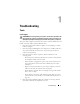
Troubleshooting Tools Power Lights CAUTION: Before working inside your computer, read the safety information that shipped with your computer. For additional safety best practices information, see the Regulatory Compliance Homepage at www.dell.com/regulatory_compliance. The power button light located on the front of the computer illuminates and blinks or remains solid to indicate different states: • If the power light is blue and the computer is not responding, see "Beep Codes" on page 10.
• • – Ensure that the voltage selection switch is set to match the AC power at your location, if applicable. – Ensure that the processor power cable is securely connected to the system board (see "System Board Components" on page 40). If the power light is steady amber, a device may be malfunctioning or incorrectly installed. – Remove and then reinstall the memory modules (see "Replacing or Adding a Memory Module" on page 104).
Code (repetitive Description short beeps) Suggested Resolution 2 No memory modules are detected. • If two or more memory modules are installed, remove the modules (see "Replacing or Adding a Memory Module" on page 104), and then reinstall one module and restart the computer. If the computer starts normally, continue to install additional memory modules (one at a time) until you have identified a faulty module or reinstalled all modules without error.
System Messages NOTE: If the message you received is not listed in the table, see the documentation for either the operating system or the program that was running when the message appeared. A L E R T ! P R E V I O U S A T T E M P T S A T B O O T I N G T H I S S YS T E M H A V E F A I L E D A T CHECKPOINT [NNNN].
2 Type hardware troubleshooter in the search field and press to start the search. 3 In the Fix a Problem section, click Hardware Troubleshooter. 4 In the Hardware Troubleshooter list, select the option that best describes the problem and click Next to follow the remaining troubleshooting steps. Windows Vista®: 1 Click the Windows Vista start button , and click Help and Support. 2 Type hardware troubleshooter in the search field and press to start the search.
The Dell Diagnostics is located on a separate diagnostic utility partition on your hard drive. NOTE: If your computer does not display a screen image, contact Dell (see "Contacting Dell" on page 137. 1 Ensure that the computer is connected to an electrical outlet that is known to be working properly. 2 Turn on (or restart) your computer. 3 When the DELL logo appears, press immediately. NOTE: Keyboard failure may result when a key is held down for extended periods of time.
9 Close the Main Menu window to exit the Dell Diagnostics and restart the computer. Starting the Dell Diagnostics From the Drivers and Utilities Disc Before running the Dell Diagnostics, enter the system setup program (see "System Setup Program" on page 129) to review your computer’s configuration information, and ensure that the device you want to test is displayed in the system setup program and is active. 1 Insert the Drivers and Utilities disc into the optical drive. 2 Restart your computer.
NOTE: It is recommended that you select Test System to run a complete test on your computer. Selecting Test Memory initiates the extended memory test, which can take up to thirty minutes or more to complete. When the test completes, record the test results and then press any key to return to the previous menu. 9 At the Dell Diagnostics Main Menu, left-click with the mouse, or press and then , to select the test you want to run (see "Dell Diagnostics Main Menu" on page 16).
Option Function Express Test Performs a quick test of devices in the system. This typically can take 10 to 20 minutes. NOTE: The Express Test requires no interaction on your part. Run Express Test first to increase the possibility of tracing a problem quickly. Extended Test Performs a thorough check of devices in the system. This typically can take an hour or more. NOTE: The Extended Test periodically requires your input to answer specific questions.
Tab Function (continued) Errors Displays error conditions encountered, error codes, and the problem description. Help Describes the test and any requirements for running the test. Configuration Displays the hardware configuration for the selected device. The Dell Diagnostics obtains configuration information for all devices from the system setup program, memory, and various internal tests, and displays the information in the device list in the left pane of the screen.
Battery Problems CAUTION: There is a danger of a new battery exploding if it is incorrectly installed. Replace the battery only with the same or equivalent type recommended by the manufacturer. Discard used batteries according to the manufacturer's instructions. CAUTION: Before you begin any of the procedures in this section, follow the safety instructions that shipped with your computer. For additional safety best practices information, see the Regulatory Compliance Homepage at www.dell.
Optical drive problems NOTE: High-speed optical drive vibration is normal and may cause noise, which does not indicate a defect in the drive or the media. NOTE: Because of different regions worldwide and different disc formats, not all DVD titles work in all DVD drives. ADJUST THE WINDOWS VOLUME CONTROL — • Click the speaker icon in the lower-right corner of your screen. • Ensure that the volume is turned up by clicking the slidebar and dragging it up.
Error Messages CAUTION: Before you begin any of the procedures in this section, follow the safety instructions that shipped with your computer. For additional safety best practices information, see the Regulatory Compliance Homepage at www.dell.com/regulatory_compliance. If the error message is not listed, see the documentation for the operating system or the program that was running when the message appeared.
NOTE: Your computer supports only IEEE 1394a standard. E N S U R E T H A T T H E C A B L E F O R T H E IEEE 1394 D E V I C E I S P R O P E R L Y I N S E R T E D I N T O THE DEVICE AND INTO THE CONNECTOR ON THE COMPUTER E N S U R E T H A T T H E IEEE 1394 D E V I C E I S E N A B L E D I N S YS T E M S E T U P — See "System Setup Program" on page 129 for assistance. E N S U R E T H A T T H E IEEE 1394 D E V I C E I S R E C O G N I Z E D B Y W I N D O W S — Windows XP: 1 Click Start and click Control Panel.
then try using the keyboard. R U N T H E H A R D W A R E TR O U B L E S H O O T E R — See "Hardware Troubleshooter" on page 12. Lockups and Software Problems CAUTION: Before you begin any of the procedures in this section, follow the safety instructions that shipped with your computer. For additional safety best practices information, see the Regulatory Compliance Homepage at www.dell.com/regulatory_compliance.
A program is designed for an earlier Windows operating system RUN THE PROGRAM COMPATIBILITY WIZARD — Windows XP: The Program Compatibility Wizard configures a program so that it runs in an environment similar to non-XP operating system environments. 1 Click Start→ All Programs→ Accessories→ Program Compatibility Wizard→ Next. 2 Follow the instructions on the screen.
COMPUTER THROUGH THE START MENU Memory Problems CAUTION: Before you begin any of the procedures in this section, follow the safety instructions that shipped with your computer. For additional safety best practices information, see the Regulatory Compliance Homepage at www.dell.com/regulatory_compliance. IF YOU RECEIVE AN INSUFFICIENT MEMORY MESSAGE — • Save and close any open files and exit any open programs you are not using to see if that resolves the problem.
• Verify that the mouse cable is connected as shown on the setup diagram for your computer. RESTART THE COMPUTER — 1 Simultaneously press to display the Start menu. 2 Press , press the up- and down-arrow keys to highlight Shut down or Turn Off, and then press . 3 After the computer turns off, reconnect the mouse cable as shown on the setup diagram. 4 Turn on the computer. TE S T T H E M O U S E — Connect a properly working mouse to the computer, and then try using the mouse.
that the network is functioning. R U N T H E H A R D W A R E TR O U B L E S H O O T E R — See "Hardware Troubleshooter" on page 12. Power Problems CAUTION: Before you begin any of the procedures in this section, follow the safety instructions that shipped with your computer. For additional safety best practices information, see the Regulatory Compliance Homepage at www.dell.com/regulatory_compliance.
• Remove and then reinstall all memory modules (see "Replacing or Adding a Memory Module" on page 104). • Remove and then reinstall any expansion cards, including graphics cards (see "PCI and PCI Express Cards" on page 59).
3 Click Properties and click Ports. 4 Adjust the settings, as needed. R E I N S T A L L T H E P R I N T E R D R I V E R — See the printer documentation for information on reinstalling the printer driver. Scanner Problems CAUTION: Before you begin any of the procedures in this section, follow the safety instructions that shipped with your computer. For additional safety best practices information, see the Regulatory Compliance Homepage at www.dell.com/regulatory_compliance.
Sound and Speaker Problems CAUTION: Before you begin any of the procedures in this section, follow the safety instructions that shipped with your computer. For additional safety best practices information, see the Regulatory Compliance Homepage at www.dell.com/regulatory_compliance. No sound from speakers NOTE: The volume control in MP3 and other media players may override the Windows volume setting. Always check to ensure that the volume on the media player(s) has not been turned down or off.
the sound is not muted. Video and Monitor Problems CAUTION: Before you begin any of the procedures in this section, follow the safety instructions that shipped with your computer. For additional safety best practices information, see the Regulatory Compliance Homepage at www.dell.com/regulatory_compliance.
C H E C K T H E D I A G N O S T I C L I G H T S — See "Power Lights" on page 9. C H E C K T H E M O N I T O R S E T T I N G S — See the monitor documentation for instructions on adjusting the contrast and brightness, demagnetizing (degaussing) the monitor, and running the monitor self-test. M O V E T H E S U B W O O F E R A W A Y F R O M T H E M O N I T O R — If your speaker system includes a subwoofer, ensure that the subwoofer is positioned at least 60 centimeters (2 feet) away from the monitor.
defective. Contact Dell (see "Contacting Dell" on page 137). Dell Technical Update Service The Dell Technical Update service provides proactive e-mail notification of software and hardware updates for your computer. The service is free and can be customized for content, format, and how frequently you receive notifications. To enroll for the Dell Technical Update service, go to support.dell.com/technicalupdate.
• View frequently asked questions. • Learn more about the Dell Support Utility. • Turn the Dell Support Utility off. Double-Clicking the Dell Support Icon Double-click the icon to manually check your computing environment, view frequently asked questions, access the help file for the Dell Support Utility, and view Dell Support settings. For more information about the Dell Support Utility, click the question mark (?) at the top of the Dell Support screen.
Working on Your Computer This document provides procedures for removing and installing the components in your computer. Unless otherwise noted, each procedure assumes that: • You have performed the steps in "Working on Your Computer" on page 35. • You have read the safety information that shipped with your computer. • When replacing a component, you have already removed the original, if installed.
NOTICE: When you disconnect a cable, pull on its connector or on its pull-tab, not on the cable itself. Some cables have connectors with locking tabs; if you are disconnecting this type of cable, press in on the locking tabs before you disconnect the cable. As you pull connectors apart, keep them evenly aligned to avoid bending any connector pins. Also, before you connect a cable, ensure that both connectors are correctly oriented and aligned.
Inside View of Your Computer Vostro™ 420 1 6 5 2 3 4 1 power supply 2 5.25-inch drive bays (3) 3 media card reader (optional) 4 I/O panel 5 3.
Vostro 220 1 6 5 2 3 4 1 38 power supply 2 5.25-inch drive bays (2) 3 media card reader (optional) 4 I/O panel 5 3.
Vostro 220s 2 1 3 6 4 5 ‘ 1 power supply 2 chassis fan 3 optical drive 4 media card reader (optional) 5 I/O panel 6 3.
System Board Components Vostro 420 1 32 2 3 31 30 4 29 28 27 26 25 24 5 23 6 7 8 22 9 21 10 20 19 18 40 17 Working on Your Computer 16 15 14 13 12 11
1 power connector (PWR2) 2 processor heat sink/fan assembly power 3 memory module connectors (4) (DIMM_1, DIMM_2, DIMM_3, DIMM_4) 4 main power connector (PWR1) 5 battery socket 6 serial ATA 5.25-inch drive connector (SATA4) 7 serial ATA hard drive connector (SATA3) 8 serial ATA hard drive connector (SATA2) 9 serial ATA hard drive connector (SATA1) 10 serial ATA hard drive connector (SATA0) 11 serial ATA 5.25-drive connector (SATA5) 12 front I/O panel connector 13 serial ATA 5.
Vostro 220 1 2 3 25 24 4 23 22 21 20 5 19 6 18 7 17 8 16 9 15 42 Working on Your Computer 14 13 12 11 10
1 power connector (PWR2) 2 processor heat sink/fan assembly power 3 memory module connectors (2) 4 main power connector (PWR1) 5 serial ATA drive connector (SATA2) 6 serial ATA drive connector (SATA1) 7 serial ATA drive connector (SATA3) 8 serial ATA drive connector (SATA0) 9 battery socket 10 front I/O panel connector 11 USB1 system board connector (from front I/O panel) 12 USB2 system board connector (from front I/O panel) 13 CMOS jumper (CLEAR CMOS) 14 USB3 system board connector 1
Vostro 220s 2 1 3 25 4 24 23 22 21 5 20 19 6 18 7 17 8 16 CLS_CMOS 9 15 44 Working on Your Computer 14 13 12 11 10
1 power connector (PWR2) 2 processor heat sink/fan assembly power 3 memory module connectors (2) 4 main power connector (PWR1) 5 serial ATA drive connector (SATA2) 6 serial ATA drive connector (SATA1) 7 serial ATA drive connector (SATA3) 8 serial ATA drive connector (SATA0) 9 battery socket 10 front I/O panel connector 11 USB1 system board connector (from front I/O panel) 12 USB2 system board connector (from front I/O panel) 13 CMOS jumper (CLEAR CMOS) 14 USB3 system board connector 1
5 Verify that the computer works correctly by running the Dell Diagnostics. See your Setup and Quick Reference Guide for help running Dell Diagnostics.
Computer Cover CAUTION: Before working inside your computer, read the safety information that shipped with your computer. For additional safety best practices information, see the Regulatory Compliance Homepage at www.dell.com/regulatory_compliance. CAUTION: To guard against electrical shock, always unplug your computer from the electrical outlet before removing the cover.
2 1 3 1 handle 3 front of computer, bezel 2 computer cover 4 Release the computer cover by grasping the handle while sliding the cover away from the front of the computer and lifting it up. Replacing the Computer Cover 1 Ensure that all cables are connected and folded out of the way. 2 Ensure that no tools or extra parts are left inside the computer. 3 Ensure that the bezel is attached to the front of the computer (see "Replacing the Bezel" on page 53).
4 Holding the cover at a slight angle, slide it toward the front of the computer until the metal clips inside the cover grip and attach securely to the chassis frame beside the front bezel. 5 Ensure that the cover is seated and aligned correctly. 6 Replace and tighten the two thumbscrews that secure the computer cover. 7 Follow the procedure in "After Working on Your Computer" on page 45.
Computer Cover
Bezel CAUTION: Before working inside your computer, read the safety information that shipped with your computer. For additional safety best practices information, see the Regulatory Compliance Homepage at www.dell.com/regulatory_compliance. CAUTION: To guard against electrical shock, always unplug your computer from the electrical outlet before removing the cover.
1 2 1 52 clips (4) Bezel 2 bezel
Replacing the Bezel 1 With the computer still on its side, align and insert the bezel hooks into the slots along one edge of the front of the computer. 2 Rotate the bezel toward the computer until the clips snap into place on the opposite edge of the front of the computer . 3 Perform the steps in the procedure "After Working on Your Computer" on page 45.
Bezel
Chassis Support Bracket CAUTION: Before working inside your computer, read the safety information that shipped with your computer. For additional safety best practices information, see the Regulatory Compliance Homepage at www.dell.com/regulatory_compliance. CAUTION: To guard against electrical shock, always unplug your computer from the electrical outlet before removing the cover. Removing the Chassis Support Bracket NOTE: Only the Vostro 220s includes a chassis support bracket.
Vostro 220s 3 2 4 1 5 6 56 1 chassis support bracket 2 flange 3 screw 4 cable clip 5 tabs (2) 6 slots (2) Chassis Support Bracket
Replacing the Chassis Support Bracket 1 Holding the bracket at an angle, insert the tabs on one end of the bracket into the slots in the chassis. 2 While holding the bracket slightly raised, slide any cables as appropriate into the cable clip for storage. 3 Lower the other end of the bracket to engage the remaining tab. 4 Rotate the flange closed and replace and tighten the securing screw.
3 2 4 1 5 6 1 chassis support bracket 2 flange 3 screw 4 cable clip 5 slots (2) 6 tabs (2) 5 Perform the steps in the procedure "After Working on Your Computer" on page 45.
PCI and PCI Express Cards CAUTION: Before working inside your computer, read the safety information that shipped with your computer. For additional safety best practices information, see the Regulatory Compliance Homepage at www.dell.com/regulatory_compliance. CAUTION: To guard against electrical shock, always unplug your computer from the electrical outlet before removing the cover.
7 If you are removing the card to replace it with a new card, proceed to step 5 in "Installing a PCI or PCI Express Card" on page 60. Otherwise, proceed to step 8. 8 If you are removing the card permanently, install a filler bracket in the empty card-slot opening at the back of the computer, using the screw you removed in step 5 to secure the filler bracket to the chassis. NOTE: Installing filler brackets over empty card-slot openings is necessary to maintain FCC certification of the computer.
See the documentation that came with the card for information on configuring the card, making internal connections, or otherwise customizing it for your computer. CAUTION: Some network adapters automatically start the computer when they are connected to a network. To guard against electrical shock, be sure to unplug your computer from its electrical outlet before installing any cards.
6 5 1 4 2 3 1 PCI Express x16 card 2 PCI Express x16 card slot 3 securing tab 4 PCI Express x1 card slot 5 PCI Express x1 card 6 securing slot 7 Align the card in the connector and press down firmly. Ensure that the card is fully seated in the connector slot. 8 Replace and tighten the screw to secure the card in the slot. 9 Connect any cables that should be attached to the card. See the documentation for the card for information about the card’s cable connections.
Configuring Your Computer After Removing or Installing a PCI or PCI Express Card NOTE: For information on installing drivers and software for your card, see the documentation that shipped with the card. Type of Card Sound Card Network Card Installed Removed 1 Enter the system setup 1 Enter the system setup program (see "System Setup Program" on page 129 for instructions). 2 Go to Integrated Peripherals, select Onboard Audio Controller, and then change the setting to Disabled.
PCI and PCI Express Cards
Drives CAUTION: Before working inside your computer, read the safety information that shipped with your computer. For additional safety best practices information, see the Regulatory Compliance Homepage at www.dell.com/regulatory_compliance. CAUTION: To guard against electrical shock, always unplug your computer from the electrical outlet before removing the cover.
b Slide the drive out of the slot, toward the back of the computer.
Vostro 220 1 4 2 3 1 screws (4) 2 hard drive 3 power cable 4 data cable 6 For the Vostro 220s: a Raise and hold the hard-drive release latch. b Slide the drive partway out of the bay, rotate the back of the drive upward until the drive is perpendicular to the drive cage, and guide the screws through the cutaway channels in the drive cage until you can lift the drive away from the computer. c Repeat step a and step b for the second hard drive, if installed.
Vostro 220s 4 3 5 2 1 1 cutaway channels (2) 2 hard-drive release latch 3 hard drive 4 screw guides (4) 5 power cable 6 data cable 7 If you are installing a replacement drive, skip to step 3 in "Replacing or Adding a Hard Drive" on page 69. If you are removing this drive permanently and the drive bay is to remain empty, proceed to step 8.
8 Disconnect the data cable from the system board (see "System Board Components" on page 40) and remove the cable from the computer. 9 Follow the procedure in "After Working on Your Computer" on page 45. 10 When you restart your computer, check the drive configuration information in the system setup program: a Enter the system setup program (see "System Setup Program" on page 129 for instructions).
Vostro 220s 4 3 2 1 1 cutaway channels (2) 2 hard-drive release latch 3 hard drive 4 screw guides (4) 5 For the Vostro 420 and Vostro 220: 70 a Slide the hard drive into the hard drive bay. b Align the holes on the side of the hard drive with the holes in the drive cage, and install the screws to secure the hard drive in the bay.
Vostro 420 1 4 2 3 1 screws (4 total: 2 screws to guide drive into slot; 2 screws to secure drive in slot) 2 hard drive 3 power cable 4 data cable Drives 71
Vostro 220 1 4 2 3 1 screws (4) 2 hard drive 3 power cable 4 data cable 6 Connect the power and data cables to the back of the drive. NOTICE: The connectors are "keyed" for correct insertion; that is, a notch or a missing pin on one connector fits with a tab or a filled-in hole on the other connector. Align the cable connectors correctly before inserting them to avoid damage to the connectors.
8 Check all cables to ensure that they are properly connected and firmly seated. 9 For the Vostro 220s, replace the chassis support bracket (see "Replacing the Chassis Support Bracket" on page 57). 10 Follow the procedure in "After Working on Your Computer" on page 45. 11 When you restart your computer, check the drive configuration information in the system setup program: a Enter the system setup program (see "System Setup Program" on page 129 for instructions).
1 3 1 screws (2) 2 2 media card reader 3 USB interface cable 4 Disconnect the USB cable from the back of the media card reader. 5 For the Vostro 420 and Vostro 220, remove the two screws securing the device to the drive cage. For the Vostro 220s, lift the release latch that secures both the optical drive and the 3.5-inch device in their respective drive cages.
2 1 3 1 release latch 3 media card reader 2 optical drive bay 6 Slide the device out through the front of the computer. 7 If you are installing a replacement device, skip to step 5 in "Replacing or Adding a Media Card Reader" on page 77. If you are removing the device permanently and the drive bay is to remain empty, proceed to step 8. 8 Disconnect the USB interface cable from the system board (see "System Board Components" on page 40), and remove the cable from the computer. 9 Install a 3.
a Holding the front-panel insert at an angle, insert one end into the drive bay opening. b Push the other end of the insert into the opening until it fits into place. NOTE: To comply with FCC regulations, install the 3.5-inch front-panel insert whenever the device is permanently removed from the computer. 1 1 3.5-inch front-panel insert 10 For the Vostro 220s, push the release latch down to resecure the optical drive.
1 2 4 3 1 tab 2 inside of bezel 3 cover for empty bay 4 slot in bezel opening 12 Replace the bezel (see "Replacing the Bezel" on page 53). 13 Follow the procedure in "After Working on Your Computer" on page 45. 14 Enter the system setup program (see "System Setup Program" on page 129 for instructions) and update the drive settings. Replacing or Adding a Media Card Reader 1 Follow the procedures in "Before Working on Your Computer" on page 35.
b For the Vostro 220s, lift the release latch that secures both the optical drive and the 3.5-inch device in their respective drive cages. c Remove the empty-bay cover from the bezel: From the inside of the bezel, press the release latch on the cover, and lift the cover from the bezel. 1 3 2 1 inside of bezel 3 cover for empty bay 2 release latch 5 Remove the media card reader from its packaging. 6 For the Vostro 220s, install two screws on each side of the media card reader.
9 For the Vostro 220s, push the release latch down to secure the optical drive and the 3.5-inch device in their respective drive cages. NOTE: Install the media card reader into the drive bay before you connect the USB interface cable to the back of the device. 10 Connect the USB interface cable to the back of the device. NOTICE: The connectors are "keyed" for correct insertion; that is, a notch or a missing pin on one connector fits with a tab or a filled-in hole on the other connector.
13 Follow the procedure in "After Working on Your Computer" on page 45. 14 See the documentation that came with the drive for instructions on installing any software required for drive operation. 15 Enter the system setup program (see "System Setup Program" on page 129 for instructions) and update the drive settings. Optical Drive CAUTION: Before working inside your computer, read the safety information that shipped with your computer.
1 2 5 4 3 1 screws (2) 2 screw holes (4) 3 optical drive 4 data cable 5 power cable 5 For the Vostro 420 and Vostro 220, remove the two screws securing the optical drive to the drive cage. 6 Slide the optical drive out through the front of the computer. 7 If you are installing a replacement drive, skip to step 5 in "Replacing or Adding an Optical Drive" on page 82. If you are removing this drive permanently and the drive bay is to remain empty, proceed to step 8.
1 2 1 screws (2) 2 5.25-inch front-panel insert NOTE: To comply with FCC regulations, install the 5.25-inch front-panel insert whenever an optical drive is permanently removed from the computer. 10 Replace the bezel (see "Replacing the Bezel" on page 53). 11 Follow the procedure in "After Working on Your Computer" on page 45. 12 Enter the system setup program (see "System Setup Program" on page 129 for instructions) and update the drive settings.
4 If you are adding an optical drive in a bay that has not had a device previously installed in it, remove the break-away metal plate (front-panel insert) from the empty drive bay (see "Removing a Drive Bay Break-Away Metal Plate" on page 85). 5 Remove the optical drive from its packaging. 6 Gently slide the optical drive into the bay from the front of the computer. 7 For the Vostro 420 and Vostro 220: a Align the screw slots in the optical drive with the screw slots on the drive cage.
1 2 3 5 4 1 screws (2) 2 screw holes 3 optical drive 4 data cable 5 power cable 10 Replace the bezel (see "Replacing the Bezel" on page 53). 11 Follow the procedure in "After Working on Your Computer" on page 45. 12 See the documentation that came with the drive for instructions on installing any software required for drive operation. 13 Enter the system setup program (see "System Setup Program" on page 129 for instructions) and update the drive settings.
Removing a Drive Bay Break-Away Metal Plate Vostro 420 and Vostro 220 Vostro 420 1 1 3.5-inch bay break-away metal plate To remove the 3.5-inch bay break-away metal plate, insert the tip of a Phillips screwdriver into the slot on the plate, and rotate the screwdriver outwards for leverage to twist and ultimately break the two metal tabs that attach the plate to the chassis. NOTE: Discard the 3.5-inch bay metal plate once it is removed. It is not designed for reuse.
still a break-away plate or whether it is attached with two screws. Remove the two screws, if installed, or use the Phillips screwdriver to break away the plate, as appropriate. 1 1 5.25-inch bay metal plate (for empty optical-drive bay NOTE: Store 5.25-inch metal plates for reuse should you decide to permanently remove an optical drive in the future. Only the break-away metal plates for the optical drive bays have screw holes for reuse.
Vostro 220s 1 1 3.
Drives
I/O Panel CAUTION: Before working inside your computer, read the safety information that shipped with your computer. For additional safety best practices information, see the Regulatory Compliance Homepage at www.dell.com/regulatory_compliance. CAUTION: To guard against electrical shock, always unplug your computer from the electrical outlet before removing the cover.
8 Ease the I/O panel away from the computer as you guide the cables through the bays, holes, and front-panel opening.
Vostro 220s 1 2 3 1 front-panel opening 2 I/O panel and cables 3 screw Replacing the I/O Panel NOTICE: Take care not to damage the cable connectors and the cable routing clip(s) (if present) when sliding the I/O panel into the computer. 1 Route the I/O panel cables into the chassis through the I/O panel opening, and guide them through the various holes and bays. 2 Slide the I/O panel cables into the cable clip(s) (if present). 3 Replace and tighten the screw that secures the I/O panel.
5 For the Vostro 220s: a Replace the chassis support bracket (see "Replacing the Chassis Support Bracket" on page 57). b Replace any hard drives in the hard drive cage (see "Replacing or Adding a Hard Drive" on page 69) that you removed in step 5 of "Removing the I/O Panel" on page 89. 6 Follow the procedure in "After Working on Your Computer" on page 45.
Fan CAUTION: Before working inside your computer, read the safety information that shipped with your computer. For additional safety best practices information, see the Regulatory Compliance Homepage at www.dell.com/regulatory_compliance. CAUTION: To guard against likelihood of electric shock, laceration from moving fan blades, or other unexpected injuries, always unplug your computer from the electrical outlet before removing the cover.
Vostro 420 1 3 2 94 1 chassis fan 3 screws (4) Fan 2 system board power connector
Vostro 220 1 3 2 1 chassis fan 3 screws (4) 2 system board power connector Fan 95
Vostro 220s 3 2 1 96 1 system board power connector 3 screw Fan 2 chassis fan
Replacing the Chassis Fan 1 For the Vostro 220s: a Lower the fan into the chassis such that the screw hole in the fan is offset and slightly forward of the screw hole in the fan mount on the chassis. b Press the fan into the side of the chassis, and then slide it toward the back of the computer until it sets against the stops. c Proceed to step 3. 2 While holding the chassis fan in place, align the screw hole(s) and install the screw(s) that secure the fan to the chassis.
Fan
Processor Heat Sink/Fan Assembly CAUTION: Before working inside your computer, read the safety information that shipped with your computer. For additional safety best practices information, see the Regulatory Compliance Homepage at www.dell.com/regulatory_compliance. CAUTION: To guard against likelihood of electric shock, laceration from moving fan blades, or other unexpected injuries, always unplug your computer from the electrical outlet before removing the cover.
1 2 6 3 5 4 100 1 Phillips screwdriver 2 heat sink/fan assembly 3 heat sink/fan cable 4 system board fan connector 5 screw holes with rubber bushings (4) 6 captive screws (4) Processor Heat Sink/Fan Assembly
Replacing the Processor Heat Sink/Fan Assembly NOTICE: Unless a new heat sink is required for the new processor, reuse the original heat sink/fan assembly when you replace the processor. 1 Apply thermal solution to the heat sink as needed. 2 Align the four captive screws on the heat sink/fan assembly with the holes and rubber bushings on the system board.
1 Phillips screwdriver 2 heat sink/fan assembly 3 heat sink/fan cable 4 system board fan connector 5 screw holes with rubber bushings 6 captive screws (4) 3 Tighten the captive screws evenly to secure the heat sink/fan assembly to the system board. NOTICE: Ensure that the assembly is correctly seated and secure. 4 Attach the heat sink/fan assembly cable to the system board (see "System Board Components" on page 40). 5 Follow the procedure in "After Working on Your Computer" on page 45.
Memory Module(s) CAUTION: Before working inside your computer, read the safety information that shipped with your computer. For additional safety best practices information, see the Regulatory Compliance Homepage at www.dell.com/regulatory_compliance. Removing Memory Modules 1 Follow the procedures in "Before Working on Your Computer" on page 35. 2 Remove the computer cover (see "Replacing the Computer Cover" on page 48).
Replacing or Adding a Memory Module NOTICE: Do not install ECC memory modules. NOTICE: If you remove your original memory modules from the computer during a memory upgrade, keep them separate from any new modules, even if you purchased the new modules from Dell. If possible, do not pair an original memory module with a new memory module. Otherwise, your computer may not start properly.
1 Align the notch on the bottom of the module with the crossbar in the connector. . 3 2 1 4 1 cutouts (2) 2 memory module 3 notch 4 crossbar NOTICE: To avoid damage to the memory module, press the module straight down into the connector while you apply equal force to each end of the module. 2 Insert the module into the connector until the module snaps into position. If you insert the module correctly, the securing clips snap into the cutouts at each end of the module.
6 Right-click the My Computer icon on your Windows® desktop and click Properties. 7 Click the General tab. 8 To verify that the memory is installed correctly and being recognized by the computer, check the amount of memory (RAM) listed.
Power Supply CAUTION: Before working inside your computer, read the safety information that shipped with your computer. For additional safety best practices information, see the Regulatory Compliance Homepage at www.dell.com/regulatory_compliance. CAUTION: To guard against electrical shock, always unplug your computer from the electrical outlet before removing the cover.
7 Press down on the power supply retention clips. 1 2 1 screws (4) (only 3 screws for Vostro 220s) 2 power supply 8 Slide the power supply toward the front of the computer and lift it out.
Replacing the Power Supply 1 Set the replacement power supply into place. 2 Replace and tighten the screws that secure the power supply to the back of the computer chassis. CAUTION: Failure to replace and tighten all screws may cause electrical shock as these screws are a key part of the grounding system. NOTICE: Route the DC power cables as you insert them into the routing clips (if present). The cables must be properly routed to prevent the cables from being damaged.
a Reinstall any PCI or PCI Express cards (see "Installing a PCI or PCI Express Card" on page 60). b Slide the optical drive back into the drive bay. c Replace the chassis support bracket (see "Replacing the Chassis Support Bracket" on page 57). 5 Follow the procedure in "After Working on Your Computer" on page 45.
Vostro 220 Power Supply 111
Vostro 220s P4 P3 P5 P1 P2 DC Power Supply Connector Pin Assignments DC Power Connector P1 13 14 15 16 17 18 19 20 21 22 23 24 1 2 3 4 5 6 7 8 9 10 11 12 Pin Number Signal name Wire Color Wire Size 1 3.3 V Orange 20 AWG 2 3.
Pin Number Signal name Wire Color Wire Size 5 RTN Black 20 AWG 6 5V Red 20 AWG 7 RTN Black 20 AWG 8 POK Gray 22 AWG 9 5 V AUX Purple 20 AWG 10 +12 V Yellow 20 AWG 11 +12 V Yellow 20 AWG 12 3.3 V Orange 20 AWG 13 3.
Pin Number Signal Name 18-AWG Wire 2 GND Black 3 +12 VADC Yellow 4 +12 VADC Yellow DC Power Connectors P3, P4, P5, P6, P7, and P8 Pin Number Signal name 18-AWG Wire 1 +3.
DC Power Connector P10 Pin Number Signal Name 22-AWG Wire 1 +12 VDC Yellow 2 +12 VDC Yellow 3 +12 VDC Yellow 4 GND Black 5 GND Black 6 GND Black Power Supply 115
Power Supply
Coin-Cell Battery CAUTION: Before working inside your computer, read the safety information that shipped with your computer. For additional safety best practices information, see the Regulatory Compliance Homepage at www.dell.com/regulatory_compliance. CAUTION: A new battery can explode if it is incorrectly installed. Replace the battery only with the same or equivalent type recommended by the manufacturer. Discard used batteries according to the manufacturer’s instructions.
1 2 1 release latch 2 battery (positive side) 5 Carefully press the release latch away from the battery to allow the battery to pop up from the socket. 6 Remove the battery from the system and properly dispose of the battery. Replacing the Coin-Cell Battery 1 Insert the new battery into the socket with the side labeled "+" facing up, and then snap the battery into place. Ensure that it is securely retained within the battery socket.
System Board CAUTION: Before working inside your computer, read the safety information that shipped with your computer. For additional safety best practices information, see the Regulatory Compliance Homepage at www.dell.com/regulatory_compliance. CAUTION: To guard against likelihood of electric shock, laceration by moving fan blades, or other unexpected injuries, always unplug your computer from the electrical outlet before removing the cover.
b Remove the memory modules from the system board (see "Replacing or Adding a Memory Module" on page 104) and place them individually into antistatic packaging. c Remove the processor from the system board (see "Removing the Processor" on page 125) and place it into antistatic packaging. 9 Disconnect the chassis fan cable from the system board. 10 Disconnect any additional cables from the system board. 11 Remove the screws that secure the system board to the computer chassis.
2 1 1 system board 2 screws (9) Replacing a System Board 1 Align the holes of the system board with the screw holes in the chassis, ensuring that the back panel connectors are properly aligned in the openings on the back of the chassis.
2 1 2 Replace the screws that secure the system board to the chassis. Avoid over-tightening the screws. CAUTION: Failure to replace and tighten all screws properly may not provide adequate grounding of the system board and result in system failures. 3 Connect the chassis fan cable to the system board. 4 If the system board is being replaced with a new system board: a 122 Install the memory modules onto the system board (see "Replacing or Adding a Memory Module" on page 104).
b Install the processor onto the system board (see "Replacing the Processor" on page 126). a Install the processor heat sink/fan assembly (see "Replacing the Processor Heat Sink/Fan Assembly" on page 101). 5 Connect the power supply cables to the system board (see "System Board Components" on page 40 for connector locations). 6 Connect all front panel cables to the system board (see "System Board Components" on page 40 for connector locations).
System Board
Processor CAUTION: Before working inside your computer, read the safety information that shipped with your computer. For additional safety best practices information, see the Regulatory Compliance Homepage at www.dell.com/regulatory_compliance. NOTICE: Do not perform the following steps unless you are familiar with hardware removal and replacement. Performing these steps incorrectly could damage your system board. For information about contacting Dell, see "Contacting Dell" on page 137.
1 2 3 5 4 1 processor cover 2 processor 3 socket 4 release lever 5 retention hook NOTICE: When replacing the processor, do not touch any of the pins inside the socket or allow any objects to fall on the pins in the socket. 6 Lift the processor to remove it from the socket and place it into antistatic packaging. Replacing the Processor NOTICE: Ground yourself by touching an unpainted metal surface, such as on the back of the computer.
NOTICE: Socket pins are delicate. To avoid damage, ensure that the processor is aligned properly with the socket, and do not use excessive force when you install the processor. Be careful not to touch or bend the pins on the system board.
NOTICE: To avoid damage, ensure that the processor aligns properly with the socket, and do not use excessive force when you press the processor into the socket. 5 Press the processor lightly into the socket until it is fully seated. 6 Lower the processor cover. NOTE: Ensure that the tab on the cover is positioned such that it will be underneath the retention latch when the release lever is rotated and secured underneath the retention hook.
System Setup Program Overview Use the system setup program as follows: • To change the system configuration information after you add, change, or remove any hardware in your computer • To set or change a user-selectable option such as the user password • To read the current amount of memory or set the type of hard drive installed Before you use the system setup program, it is recommended that you write down the system setup screen information for future reference.
System Setup Program Screens The system setup program screen displays current or changeable configuration information for your computer. Information on the screen is divided into three areas: the options list, active options field, and key functions. Options List — This field appears on the left side of the system setup program window. The field is a scrollable list containing features that define the configuration of your computer, including installed hardware, power conservation, and security features.
System Info System Info Lists system information such as the computer name, and other system-specific information. BIOS Info Shows the BIOS version number and date information. Service Tag Displays computer service tag number for support purposes. CPU Info Identifies whether the computer’s processor supports Hyper-Threading and lists the processor type, processor bus speed, processor ID, clock speed, and L2 cache.
Hard Disk Boot Priority Used to set the device priority of hard drives. The items displayed are dynamically updated according to the hard drives detected. Removable Drives Boot Priority Used to set the device priority of removable devices such a media card readers. The items displayed are dynamically updated according to the removable devices connected.
Load Optimal Defaults Resets CMOS defaults to factory install values. Boot Sequence This feature allows you to change the boot sequence for devices. Option Settings • Diskette Drive — The computer attempts to boot from a floppy drive (if installed). If the floppy disk in the drive is not bootable, if no floppy disk is in the drive, or if there is no floppy drive installed in the computer, the computer generates an error message. • Hard Drive — The computer attempts to boot from the primary hard drive.
3 When F2 = Setup, F12 = Boot Menu appears in the upper-right corner of the screen, press . If you wait too long and the operating system logo appears, continue to wait until you see the Microsoft Windows desktop. Then shut down your computer and try again. The Boot Device Menu appears, listing all available boot devices. Each device has a number next to it. 4 At the bottom of the menu, enter the number of the device that is to be used for the current boot only.
4 Remove the 2-pin jumper plug from pins 2 and 3 and fix it on pins 1 and 2. 5 Wait for approximately five seconds to clear the password. 6 Remove the 2-pin jumper plug from pins 1 and 2 and replace it on pins 2 and 3 to enable the password feature. 7 Follow the procedure in "After Working on Your Computer" on page 45. Clearing CMOS Settings CAUTION: Before working inside your computer, read the safety information that shipped with your computer.
BIOS The system setup program resides within the BIOS on the system board. If you install a new system board, you may need to update (or flash) the BIOS. Flashing the BIOS From the Hard Drive 1 Turn on the computer. 2 Locate the latest BIOS update file for your computer at support.dell.com. 3 Click Download Now to download the file. 4 If the Export Compliance Disclaimer window appears, click Yes, I Accept this Agreement. The File Download window appears.
Contacting Dell To contact Dell for sales, technical support, or customer service issues: 1 Visit support.dell.com. 2 Verify your country or region in the Choose a Country/Region drop-down menu at the bottom of the page. 3 Click Contact Us on the left side of the page. 4 Select the appropriate service or support link based on your need. 5 Choose the method of contacting Dell that is convenient for you.
Contacting Dell