Dell™ 500 Service Manual Before You Begin Optical Drive Hard Drive Center Control Cover Internal Card With Bluetooth® Wireless Technology Keyboard Button Board Memory Wireless Mini-Card Speaker Assembly Display Palm Rest ExpressCard Cage Processor Thermal-Cooling Assembly Processor Module System Board Assembly Coin-Cell Battery Battery Latch Assembly Flashing the BIOS Pin Assignments for I/O Connectors Notes, Notices, and Cautions NOTE: A NOTE indicates important information that helps you make better use
Back to Contents Page Before You Begin Dell™ 500 Service Manual Recommended Tools Before Working Inside Your Computer This document provides procedures for removing and installing the components in your computer. Unless otherwise noted, each procedure assumes that: You have performed the steps in Before Working Inside Your Computer. You have read the safety information in your Dell Product Information Guide. When replacing a component, you have already removed the original, if installed.
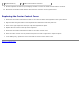
NOTE: Ensure that the computer is off and not in a power management mode. If you cannot shut down the computer using the operating system, press and hold the power button for 4 seconds. 3. Disconnect your computer and all attached devices from their electrical outlets. NOTICE: To disconnect a network cable, first unplug the cable from your computer, and then unplug it from the network wall jack. 4. Disconnect any telephone or network cables from the computer. 5.
Back to Contents Page Optical Drive Dell™ 500 Service Manual Removing the Optical Drive 1. Follow the procedures in Before You Begin. 2. Turn the computer over. 3. Remove the locking screw from the optical drive. 4. Using a plastic scribe or screwdriver, push the notch to release the optical drive from the bay. 5. Slide the optical drive out of the bay. 1 locking screw 2 notch Replacing the Optical Drive 1. Slide the optical drive into the bay. 2. Replace and tighten the locking screw.
Back to Contents Page Hard Drive Dell™ 500 Service Manual CAUTION: Before you begin any of the procedures in this section, follow the safety instructions in the Product Information Guide. CAUTION: Do not touch the metal housing of the hard drive if you remove the hard drive from the computer while the drive is hot. NOTICE: To prevent data loss, turn off your computer before removing the hard drive. Do not remove the hard drive while the computer is on or in Sleep state.
1 hard drive cover 2 screws (2) 3 hard drive Replacing the Hard Drive CAUTION: Before you begin any of the procedures in this section, follow the safety instructions in the Product Information Guide. NOTICE: Hard drives are extremely fragile. Exercise care when handling the hard drive. 1. Replace the hard drive cover and tighten the two screws to secure the cover to the hard drive. NOTICE: Use firm and even pressure to slide the hard drive into place. Excessive force may result in damage to the connector.
Back to Contents Page Center Control Cover Dell™ 500 Service Manual CAUTION: Before you begin any of the procedures in this section, follow the safety instructions in the Product Information Guide. NOTICE: To avoid electrostatic discharge, ground yourself by using a wrist grounding strap or by periodically touching an unpainted metal surface (such as a connector on the back of the computer).
1 center control cover 2 scribe 3 media control buttons connector 6. Disconnect the cable from the media control buttons connector located underneath the center control cover. 7. Remove the center control cover. 8. Remove the two screws from the top of the keyboard. NOTICE: The key caps on the keyboard are fragile, easily dislodged, and time-consuming to replace. Be careful when removing and handling the keyboard.
3 keyboard tabs (5) 4 media control buttons connector 9. Lift the keyboard and hold it up and slightly forward to access the media control buttons connector. 10. Disconnect the media control buttons cable from the connector on the system board. Replacing the Center Control Cover 1. Reconnect the media control buttons cable to the connector below the keyboard on the system board. 2. Align the tabs along the bottom of the keyboard and slide them under the palm rest. 3.
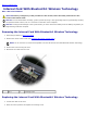
Back to Contents Page Internal Card With Bluetooth® Wireless Technology Dell™ 500 Service Manual CAUTION: Before you begin any of the procedures in this section, follow the safety instructions in the Product Information Guide. NOTICE: To avoid electrostatic discharge, ground yourself by using a wrist grounding strap or by periodically touching an unpainted metal surface (such as a connector on the back of the computer).
3. Replace the center control cover (see Replacing the Center Control Cover).
Back to Contents Page Keyboard Dell™ 500 Service Manual CAUTION: Before you begin any of the procedures in this section, follow the safety instructions in the Product Information Guide. NOTICE: To avoid electrostatic discharge, ground yourself by using a wrist grounding strap or by periodically touching an unpainted metal surface (such as a connector on the back of the computer).
Replacing the Keyboard 1. Slide the keyboard cable into the keyboard connector. 2. Rotate the keyboard connector latch to secure the cable. 3. Align the tabs along the bottom of the keyboard and slide them under the palm rest. 4. Press on the top right edge to snap the keyboard into place. 5. Replace the two screws on the top of the keyboard. 6. Replace the center control cover (see Replacing the Center Control Cover).
Back to Contents Page Button Board Dell™ 500 Service Manual CAUTION: Before you begin any of the procedures in this section, follow the safety instructions in the Product Information Guide. NOTICE: To avoid electrostatic discharge, ground yourself by using a wrist grounding strap or by periodically touching an unpainted metal surface (such as a connector on the back of the computer).
4. Replace the center control cover (see Replacing the Center Control Cover).
Back to Contents Page Memory Dell™ 500 Service Manual CAUTION: Before you begin any of the procedures in this section, follow the safety instructions in the Product Information Guide. You can increase your computer memory by installing memory modules on the system board. See "Specifications" in your Owner's Manual for information on the memory supported by your computer. Install only memory modules that are intended for your computer.
securing clips. NOTICE: To avoid electrostatic discharge, ground yourself by using a wrist grounding strap or by periodically touching an unpainted metal surface (such as a connector on the back of the computer). 3. Use your fingertips to carefully spread apart the securing clips on each end of the memory module connector until the module pops up. 4. Remove the module from the connector.
NOTICE: If the cover is difficult to close, remove the module and reinstall it. Forcing the cover to close may damage your computer. 3. Replace the bottom cover and tighten the eight captive screws. 4. Insert the battery into the battery bay, or connect the AC adapter to your computer and an electrical outlet. 5. Turn on the computer. As the computer boots, it detects the additional memory and automatically updates the system configuration information.
Back to Contents Page Wireless Mini-Card Dell™ 500 Service Manual CAUTION: Before you begin any of the procedures in this section, follow the safety instructions in the Product Information Guide. NOTICE: To help prevent damage to the system board, you must remove the battery from the battery bay before you begin working inside the computer. If you ordered a wireless Mini-Card with your computer, the card is already installed. Your computer supports Wireless Local Area Network (WLAN) Mini-Card.
1 antenna cable connectors 2 securing screw 5. Release the Mini-Card by removing the securing screw. 6. Lift the card out of its system board connector. 1 Mini-Card Replacing Mini-Card NOTICE: The connectors are keyed to ensure correct insertion. If you feel resistance, check the connectors on the card and on the system board, and realign the card. NOTICE: To avoid damage to the Mini-Card, never place cables under the card.
1. Insert the card connector into the system board connector at a 45-degree angle. 2. Press the other end of the card down into the slot on the system board until the card clicks into place. 3. Replace the securing screw. 4. Connect the cables to the Mini-Card, ensuring that you route the cables correctly. NOTE: For more specific information about which cable to connect to which connector, see the documentation that came with your Mini-Card. 5. Secure unused antenna cables in the protective mylar sleeve. 6.
Back to Contents Page Speaker Assembly Dell™ 500 Service Manual Removing the Speaker Assembly CAUTION: Before you begin the following procedure, follow the safety instructions in the Product Information Guide. 1. Follow the instructions in Before You Begin. 2. Remove the center control cover (see Removing the Center Control Cover). 3. Remove the keyboard (see Removing the Keyboard). 4. Remove the Mini-Card (see Removing Mini-Card). 5. Disconnect the speaker cable connector from the system board. 6.
5. Replace the Mini-Card (see Replacing Mini-Card). 6. Replace the keyboard (see Replacing the Keyboard). 7. Replace the center control cover (see Replacing the Center Control Cover).
Back to Contents Page Display Dell™ 500 Service Manual Display Assembly Display Bezel Display Panel Display Assembly Removing the Display Assembly CAUTION: Before you begin the following procedure, follow the safety instructions in the Product Information Guide. 1. Follow the instructions in Before You Begin. 2. Loosen the eight captive screws on the bottom cover and remove it. 3. Disconnect the antenna cables from the Mini-Card. 4.
6. Remove the center control cover (see Removing the Center Control Cover). 7. Remove the keyboard (see Removing the Keyboard). 8. Disconnect the display cable from the connector. 1 display cable 9. Pull the antenna cables from the routing hole and release them from the routing channel. 10. Remove the four screws from the display assembly hinges.
1 display assembly 2 antenna cables 3 display cable 4 hinge screws (4) 11. Lift the display assembly out of the computer. Replacing the Display Assembly CAUTION: Before you begin the following procedure, follow the safety instructions in the Product Information Guide. 1. Follow the instructions in Before You Begin. 2. Align the display hinges with the holes in the base of the computer, then lower the display into place. 3. Replace and tighten the four display assembly hinge screws. 4.
10. Replace and tighten the two screws securing the display assembly to the bottom of the computer. 11. Replace the Mini-Card and connect the antenna cables to it (see Replacing Mini-Card). 12. Replace the bottom cover and tighten the eight captive screws on the cover. Display Bezel Removing the Display Bezel CAUTION: Before you begin the following procedure, follow the safety instructions in the Product Information Guide. 1. Follow the instructions in Before You Begin. 2.
7. Starting from the bottom corner of the display panel, use your fingers to pry the bezel from the top cover, then lift the inside edges to separate the remainder of the bezel. Replacing the Display Bezel CAUTION: Before you begin the following procedure, follow the safety instructions in the Product Information Guide. 1. Follow the instructions in Before You Begin. 2. Starting at any corner, use your fingers to gently snap the bezel into place to secure it to the display panel. 3.
1 screws (2) 2 display panel 7. Lift the display panel out of the display cover. 8. Remove the eight screws (four on each side of the display panel) securing the two brackets to the display panel and remove the brackets. 1 display panel 2 screws (8) 9. Use the pull tab to disconnect the bottom flex-cable connector from the inverter connector. 10. Lift the tape securing the top flex-cable connector and gently pull to disconnect the top flex-cable connector from the display locking connector.
1 display panel 2 top flex-cable connector 3 bottom flex-cable connector Replacing the Display Panel CAUTION: Before you begin the following procedure, follow the safety instructions in the Product Information Guide. 1. Follow the instructions in Before You Begin. 2. Connect the top flex-cable connector to the display connector. 3. Connect the bottom flex-cable connector to the inverter connector. 4.
Back to Contents Page Palm Rest Dell™ 500 Service Manual Removing the Palm Rest CAUTION: Before you begin the following procedure, follow the safety instructions in the Product Information Guide. 1. Follow the instructions in Before You Begin. 2. Remove the center control cover (see Removing the Center Control Cover). 3. Remove the keyboard (see Removing the Keyboard). 4.
NOTICE: Do not use force to separate the palm rest from the computer. If you encounter resistance, gently flex or apply pressure to the palm rest, or move along the edge, working away from the area of resistance, until the palm rest is free. 1 screws (2) 2 palm rest 3 touch pad connector 4 device status lights connector 11. Moving from left to right, carefully lift the palm rest along the rear edge, near the hinge brackets, then gently lift the palm rest to remove it from the computer.
Back to Contents Page
Back to Contents Page ExpressCard Cage Dell™ 500 Service Manual Removing the ExpressCard Cage CAUTION: Before you begin the following procedure, follow the safety instructions in the Product Information Guide. 1. Follow the instructions in Before You Begin. 2. Remove the center control cover (see Removing the Center Control Cover). 3. Remove the keyboard (see Removing the Keyboard). 4. Remove the display assembly (see Removing the Display Assembly). 5. Remove the palm rest (see Removing the Palm Rest).
5. Replace the display assembly (see Replacing the Display Assembly). 6. Replace the keyboard (see Replacing the Keyboard). 7. Replace the center control cover (see Replacing the Center Control Cover).
Back to Contents Page Processor Thermal-Cooling Assembly Dell™ 500 Service Manual Removing the Processor Thermal-Cooling Assembly CAUTION: Before you begin the following procedure, follow the safety instructions in the Product Information Guide. 1. Follow the instructions in Before You Begin. 2. Turn the computer over. 3. Remove the eight captive screws securing the bottom cover and remove it. 1 module cover 2 captive screws (8) 4.
1 captive screws (5) 2 processor thermal-cooling assembly Replacing the Processor Thermal-Cooling Assembly CAUTION: Before you begin the following procedure, follow the safety instructions in the Product Information Guide. 1. Align the five captive screws on the processor thermal-cooling assembly with the screw holes on the system board. 2. In sequential order, tighten the five captive screws to secure the processor thermal-cooling assembly to the system board. 3.
Back to Contents Page System Board Assembly Dell™ 500 Service Manual USB Board Charger Board The BIOS chip in the system board contains the Service Tag, which is also visible on a barcode label on the bottom of the computer. The replacement kit for the system board includes media that provides a utility for transferring the Service Tag to the replacement system board.
1 processor heat sink fan cable connector 2 button board cable connector 3 speaker cable connector 4 wireless sniffer board connector 5 system board 18. Remove the four screws from the top of the system board. NOTE: Depending on your system configuration, the number of screws shown here may be greater than the number of screws present in your computer. 19. Lift the right side of the system board, and then carefully lift the system board out of the computer.
Replacing the System Board Assembly CAUTION: Before you begin the following procedure, follow the safety instructions in the Product Information Guide. NOTICE: Ensure that any loose cables do not get caught beneath the system board. 1. Insert the right side of the system board into the base of the computer at an angle until the connectors on the system board are aligned with the holes on the base of the computer, then carefully lower the system board into place. 2.
CAUTION: Before you begin the following procedure, follow the safety instructions in the Product Information Guide. 1. Align the USB board to the system board in the right direction and gently press to connect the USB connector to the system board. 2. Replace the screw securing the USB board to the system board assembly. 3. Follow the steps in Removing the USB Board in the reverse order.
1 screws (2) 2 charger board connector 3 charger board 4 system board Replacing the Charger Board CAUTION: Before you begin the following procedure, follow the safety instructions in the Product Information Guide. 1. Align the charger board to the system board in the right direction and gently press to connect the charger board connector to the system board. 2. Replace the two screws securing the charger board to the system board assembly. 3.
Back to Contents Page Coin-Cell Battery Dell™ 500 Service Manual Removing the Coin-Cell Battery CAUTION: Before you begin any of the procedures in this section, follow the safety instructions in the Product Information Guide. 1. Follow the instructions in Before You Begin. 2. Remove all memory modules (see Removing Memory Module(s)). 3. Remove the hard drive (see Removing the Hard Drive). 4. Remove the optical drive (see Removing the Optical Drive). 5. Remove Mini-Card (see Removing Mini-Card). 6.
1 system board 2 slot 3 coin-cell battery Replacing the Coin-Cell Battery CAUTION: Before you begin the following procedure, follow the safety instructions in the Product Information Guide. 1. Hold the coin-cell battery with the positive side up. 2. Slide the coin-cell battery into the slot and gently press until it snaps to the slot. 3. Follow the steps in Removing the Coin-Cell Battery in the reverse order.
Back to Contents Page Battery Latch Assembly Dell™ 500 Service Manual Removing the Battery Latch Assembly CAUTION: Before you begin the following procedure, follow the safety instructions in the Product Information Guide. 1. Follow the instructions in Before You Begin. 2. Remove all memory modules (see Removing Memory Module(s)). 3. Remove the hard drive (see Removing the Hard Drive). 4. Remove the optical drive (see Removing the Optical Drive). 5. Remove Mini-Card (see Removing Mini-Card). 6.
1 plastic grips 2 battery latch assembly 3 spring Replacing the Battery Latch Assembly CAUTION: Before you begin the following procedure, follow the safety instructions in the Product Information Guide. NOTICE: Ensure the battery latch assembly is properly oriented. The indent for the screw should face up when installing the assembly. 1. Slide the battery latch assembly into place. 2. Replace the spring. 3.
Back to Contents Page Flashing the BIOS Dell™ 500 Service Manual If a BIOS-update program CD is provided with a new system board, flash the BIOS from the CD. If you do not have a BIOSupdate program CD, flash the BIOS from the hard drive. Flashing the BIOS From a CD NOTICE: Plug the AC adapter into a known, good power source to prevent loss of power. Failure to do so may cause system damage. 1. Ensure that the AC adapter is plugged in and that the main battery is installed properly.
The Save In window appears. 7. Click the down arrow to view the Save In menu, select Desktop, and then click Save. The file downloads to your desktop. 8. Click Close if the Download Complete window appears. The file icon appears on your desktop and is titled the same as the downloaded BIOS update file. NOTICE: Do not interrupt this process once it begins. Doing so may cause system damage. 9. Double-click the file icon on the desktop and follow the instructions on the screen.
Back to Contents Page Processor Module Dell™ 500 Service Manual Removing the Processor Module CAUTION: Before you begin the following procedure, follow the safety instructions in the Product Information Guide. 1. Follow the instructions in Before You Begin. 2. Remove the processor thermal-cooling assembly (see Removing the Processor Thermal-Cooling Assembly). NOTICE: To avoid damage to the processor, hold the screwdriver so that it is perpendicular to the processor when turning the cam screw. 3.
Replacing the Processor Module CAUTION: Before you begin the following procedure, follow the safety instructions in the Product Information Guide. NOTICE: Do not touch the processor die. Press and hold the processor down on the substrate on which the die is mounted while turning the cam screw to prevent intermittent contact between the cam screw and processor. NOTICE: Ensure that the cam lock is in the fully open position before seating the processor module.
Back to Contents Page
Back to Contents Page Pin Assignments for I/O Connectors Dell™ 500 Service Manual USB Connector Pin Signal 1 USB5V+ 2 USBP– 3 USBP+ 4 GND Video Connector Pin Signal Pin Signal 1 CRT_R 9 5V+ 2 CRT_G 10 GND 3 CRT_B 11 MONITOR_DETECT– 4 NC 12 DDC_DATA 5 GND 13 CRT_HS 6 GND 14 CRT_VS 7 GND 15 DDC_CLK 8 GND
1394 Connector Pin Signal 1 TPB- 2 TPB+ 3 TPA- 4 TPA+ Back to Contents Page
Back to Contents Page Dell™ 500 Service Manual Notes, Notices, and Cautions NOTE: A NOTE indicates important information that helps you make better use of your computer. NOTICE: A NOTICE indicates either potential damage to hardware or loss of data and tells you how to avoid the problem. CAUTION: A CAUTION indicates potential for property damage, personal injury, or death. Information in this document is subject to change without notice. © 2008 Dell Inc. All rights reserved.