Dell™ Vostro™ A100/A180 Service Manual Technical Overview Before You Begin Replacing the Computer Cover Replacing Memory Module(s) Replacing Drives Replacing the Processor Fan and Heat Sink Assembly (Dell™ Vostro™ A180 Only) Replacing the Processor (Dell™ Vostro™ A180 only) Replacing the Front Panel Replacing the Front I/O Panel Replacing the System Board Replacing the Power Supply Replacing the Battery System Setup Model DCMTLF Notes, Notices, and Cautions NOTE: A NOTE indicates important information
Back to Contents Page Before You Begin Dell™ Vostro™ A100/A180 Service Manual Technical Specifications Recommended Tools Turning Off Your Computer Safety Instructions This chapter provides procedures for removing and installing the components in your computer. Unless otherwise noted, each procedure assumes that the following conditions exist: l You have performed the steps in Turning Off Your Computer and Safety Instructions.
. Disconnect all telephone or network cables from the computer. 4. Disconnect your computer and all attached devices from their electrical outlets. 5. Press and hold the power button while the system is unplugged to ground the system board. NOTICE: Before touching anything inside your computer, ground yourself by touching an unpainted metal surface, such as the metal at the back of the computer.
Back to Contents Page Replacing the Battery Dell™ Vostro™ A100/A180 Service Manual CAUTION: Before working inside your computer, read the safety information that shipped with your computer. For additional safety best practices information, see the Regulatory Compliance Homepage at www.dell.com/regulatory_compliance. CAUTION: A new battery can explode if it is incorrectly installed. Replace the battery only with the same or equivalent type recommended by the manufacturer.
Back to Contents Page Replacing the Computer Cover Dell™ Vostro™ A100/A180 Service Manual CAUTION: Before working inside your computer, read the safety information that shipped with your computer. For additional safety best practices information, see the Regulatory Compliance Homepage at www.dell.com/regulatory_compliance.
Back to Contents Page Replacing the Processor (Dell™ Vostro™ A180 only) Dell™ Vostro™ A100/A180 Service Manual CAUTION: Before working inside your computer, read the safety information that shipped with your computer. For additional safety best practices information, see the Regulatory Compliance Homepage at www.dell.com/regulatory_compliance. NOTICE: Do not perform the following steps unless you are familiar with hardware removal and replacement.
1 processor cover 2 tab 3 processor 4 socket 5 center cover latch 6 release lever 7 front alignment notch 8 processor pin-1 indicator 9 rear alignment notch 9. If the release lever on the socket is not fully extended, move it to that position. NOTICE: Socket pins are delicate. To avoid damage, ensure that the processor is aligned properly with the socket, and do not use excessive force when you install the processor. Be careful not to touch or bend the pins on the system board.
Back to Contents Page Replacing Drives Dell™ Vostro™ A100/A180 Service Manual Replacing a Hard Drive Replacing an Optical Drive CAUTION: Before working inside your computer, read the safety information that shipped with your computer. For additional safety best practices information, see the Regulatory Compliance Homepage at www.dell.com/regulatory_compliance. NOTE: The system does not support IDE devices.
11. Ensure that all the cables are properly connected and firmly seated. 12. Replace the computer cover on both the sides (see Replacing the Computer Cover). 13. Connect your computer and devices to electrical outlets, and then turn them on. Replacing an Optical Drive 1. Follow the procedures in Before You Begin. 2. Remove the computer cover (see Replacing the Computer Cover). 3. Disconnect the power cable and the optical drive data cable from the drive.
Back to Contents Page Replacing the Processor Fan and Heat Sink Assembly (Dell™ Vostro™ A180 Only) Dell™ Vostro™ A100/A180 Service Manual CAUTION: Before working inside your computer, read the safety information that shipped with your computer. For additional safety best practices information, see the Regulatory Compliance Homepage at www.dell.com/regulatory_compliance.
11. Replace the computer cover (see Replacing the Computer Cover). 12. Connect your computer and devices to an electrical outlet, and turn them on.
Back to Contents Page Replacing the Front Panel Dell™ Vostro™ A100/A180 Service Manual CAUTION: Before working inside your computer, read the safety information that shipped with your computer. For additional safety best practices information, see the Regulatory Compliance Homepage at www.dell.com/regulatory_compliance. 1. Follow the procedures in Before You Begin. 2. Remove the computer cover from both the sides (see Replacing the Computer Cover). 3.
Back to Contents Page Replacing the Front I/O Panel Dell™ Vostro™ A100/A180 Service Manual CAUTION: Before working inside your computer, read the safety information that shipped with your computer. For additional safety best practices information, see the Regulatory Compliance Homepage at www.dell.com/regulatory_compliance. 1. Follow the procedures in Before You Begin. 2. Remove the computer cover (see Replacing the Computer Cover). 3.
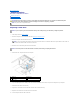
Back to Contents Page Replacing Memory Module(s) Dell™ Vostro™ A100/A180 Service Manual CAUTION: Before working inside your computer, read the safety information that shipped with your computer. For additional safety best practices information, see the Regulatory Compliance Homepage at www.dell.com/regulatory_compliance. 1. Follow the procedures in Before You Begin. 2. Remove the computer cover (see Replacing the Computer Cover). 3.
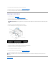
1 cutouts (2) 2 memory module 3 notch 4 tab NOTICE: To avoid damage to the memory module, press the module straight down into the connector while you apply equal force to each end of the module. 8. Insert the module into the connector until the module snaps into position. If you insert the module correctly, the securing clips snap into the cutouts at each end of the module. 9. Replace the computer cover (see Replacing the Computer Cover). 10.
Back to Contents Page Replacing the Power Supply Dell™ Vostro™ A100/A180 Service Manual CAUTION: Before working inside your computer, read the safety information that shipped with your computer. For additional safety best practices information, see the Regulatory Compliance Homepage at www.dell.com/regulatory_compliance.
Back to Contents Page
Back to Contents Page Replacing the System Board Dell™ Vostro™ A100/A180 Service Manual CAUTION: Before working inside your computer, read the safety information that shipped with your computer. For additional safety best practices information, see the Regulatory Compliance Homepage at www.dell.com/regulatory_compliance. NOTICE: Do not perform the following steps unless you are familiar with hardware removal and replacement. Performing these steps incorrectly could damage your system board.
7. Lift the system board away from the chassis. NOTICE: If you are replacing the system board, visually compare the replacement system board to the existing system board to ensure that you have the correct part. NOTE: Some components and connectors on replacement system boards may be in different locations than corresponding connectors on the existing system board. NOTE: Jumper settings on replacement system boards are preset at the factory. 8.
Back to Contents Page System Setup Dell™ Vostro™ A100/A180 Service Manual Overview Clearing CMOS Settings Flashing the BIOS Overview Use system setup to: l Change the system configuration information after you add, change, or remove any hardware in your computer l Set or change a user-selectable option such as the user password l Read the current amount of memory or set the type of hard drive installed NOTICE: Unless you are an expert computer user, do not change the settings for this
All Error; All, But Keyboard (All, But Keyboard by default) Halt On Advanced BIOS Features CPU Configuration l l Execute-Disable Bit — Disabled; Enabled (Enabled by default) Hyper Threading Technology — Disabled; Enabled (Enabled by default) Allows BIOS to skip certain tests while booting Quick Boot Disabled; Enabled (Enabled by default) Off; On (On by default) Boot Up NumLock Boot Device Configuration Hard Disk Drives Specifies the boot device priority sequence from available hard drives Removab
installed Memory Available Shows the amount of memory available Memory Speed Shows the clock speed of the memory installed Memory Channel Mode Shows the type of memory channel Memory Technology Shows the type of memory installed Standard CMOS Features System Date Displays current date settings in mm:dd:yy format System Time Displays current time settings in hh:mm:ss format IDE Channel 0 Master Displays the status of auto detection of IDE devices Hard Disk; CD/DVD; None IDE Channel 0 Slave Dis
This feature allows you to change the boot sequence for devices. Boot Options l Hard Drive — The computer attempts to boot from the primary hard drive. If no operating system is on the drive, the computer generates an error message. l CD/DVD Drive — The computer attempts to boot from the CD/DVD drive. If no CD/DVD is in the drive, or if the CD/DVD has no operating system, the computer generates an error message.
c. Place the jumper plug on the CMOS jumper (CLR_CMOS) pins 1 and 2 and wait approximately five seconds. d. Remove the jumper plug and replace it on the CMOS jumper (CLR_CMOS) pins 2 and 3. Vostro A100 Vostro A180 4. Replace the computer cover (see Replacing the Computer Cover). 5. Connect your computer and devices to electrical outlets, and turn them on. Flashing the BIOS The BIOS may require flashing when an update is available or when replacing the system board. 1.
The Save In window appears. 6. Click the down arrow to view the Save In menu, select Desktop, and then click Save. The file downloads to your desktop. 7. Click Close when the Download Complete window appears. The file icon appears on your desktop and is titled the same as the download BIOS update file. 8. Double-click the file icon on the desktop and follow the instructions on the screen.
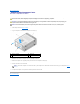
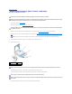
Back to Contents Page Technical Overview Dell™ Vostro™ A100/A180 Service Manual Inside View of Your Computer System Board Components CAUTION: Before working inside your computer, read the safety information that shipped with your computer. For additional safety best practices information, see the Regulatory Compliance Homepage at www.dell.com/regulatory_compliance.
1 processor (CPU) 2 memory module connector (DIMM_1) 3 main power connector (ATX_POWER) 4 serial ATA drive connector (SATA2) 5 serial ATA drive connector (SATA1) 6 front panel connector (FP1) 7 PCI connector (PCI 2.
1 processor socket (CPU) 2 processor fan connector (CPU_FAN) 3 memory module connector (DIMM_1) 4 memory module connector (DIMM_2) 5 main power connector (ATX_POWER) 6 chassis fan connector 7 serial ATA drive connector (SATA4) 8 serial ATA drive connector (SATA2) 9 clear CMOS jumper (CLR_CMOS) 10 serial ATA drive connector (SATA3) 11 serial ATA drive connector (SATA1) 12 Front panel connector (FP1) 13 front USB connector (F_USB2) 14 front USB connector (F_USB1) 15 floppy drive connect
Back to Contents Page Dell™ Vostro™ A100/A180 Service Manual NOTE: A NOTE indicates important information that helps you make better use of your computer. NOTICE: A NOTICE indicates either potential damage to hardware or loss of data and tells you how to avoid the problem. CAUTION: A CAUTION indicates a potential for property damage, personal injury, or death. Information in this document is subject to change without notice. © 2008 Dell Inc. All rights reserved.