
Deployment Guide


8 | W-7010 Controller Dell Networking W-7010 Controller | Installation Guide
W-7010 Components
This section introduces the different components and its location in the W-7010 controller.
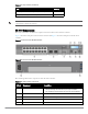
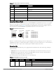
Figure 1 shows the front panel of the W-7010 controller and Figure 2 shows the back panel of the W-7010
controller.
Figure 1 Front Panel of the W-7010 Controller
Figure 2 Back Panel of the W-7010 Controller
The following table lists the components of the W-7010 controller:
Dell Safety, Environmental, and Regulatory Information (printed) 1
Dell Warranty and Support Information (printed) 1
Table 4 Package Contents (Continued)
Item Quantity
NOTE: Optional accessories are available for use with the W-7010 controller, and are sold separately. Contact your Dell sales
representative for details and assistance.
Table 5 W-7010 Controller Components
Callout Component Description
1 Access Ports 16 x10/100/1000BASE-T Ethernet ports
Orange numbering: Indicates that the port supports PoE/PoE+
Gray numbering: Indicates that the port does not support PoE/PoE+
2 Uplink Ports 2 x 1000BASE-X ports
3 Power, Status, and Peered LEDs Provides basic monitoring of the controller
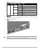
4 LCD Allows configuration of LCD behavior and other basic operations
5 Menu Button Allows selection of the LCD screen menu