
Deployment Guide


Dell Networking W-7010 Controller | Installation Guide W-7010 Controller | 9
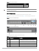
Access Ports (Ethernet Ports)
The W-7010 controller is equipped with sixteen 10/100/1000BASE-T Gigabit Ethernet ports (0 to 15). Gigabit
Ethernet uses all eight wires and each pair is bi-directional, which means, the same pair is used for both data
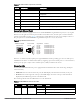
transmission and data reception. Figure 3 illustrates the Gigabit Ethernet port pin-out for an RJ-45 connector.
The pins paired on a 10/100/1000BASE-T Gigabit Ethernet port are: 1/2, 3/6, 4/5, and 7/8.
Figure 3 Gigabit Ethernet Port Pin-Out
All Power over Ethernet (PoE) capable ports support IEEE 802.3af PoE, providing up to 15.4 W of DC power,
and IEEE 802.3at Power over Ethernet Plus (PoE+), supplying up to 30.0 W of DC power to connected devices,
but the power per port is subject to the total PoE power (150W) available in the chassis.
Ethernet Port LEDs
Each 10/100/1000BASE-T Ethernet port is equipped with two LEDs that allow basic monitoring of link/port
status and activity.
LINK/ACT: Placed on the left side of the port, this LED displays the link status and activity of the port.
STATUS: Placed on the right side of the port, this LED displays the status of the port. The information
displayed by this LED changes based on the LCD mode.
The following table describes the LED behavior for each LCD mode:
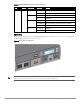
6 Enter Button Allows execution of actions on the LCD Screen
7 USB Interface 2 x USB 2.0, USB storage device can be used to save and upload
configurations
8 Management Port Allows connection to a separate management network
9 Mini-USB Console Port Provides console access for direct local access
10 Console Port RJ-45 serial console access port
11 AC in AC power connector
12 Grounding Points Provided for attaching the grounding screws
Table 6 10/100/1000BASE-T Ethernet Port LEDs
LED Function LCD Mode Indicator Status
LINK/ACT Link status N/A Green (Solid) Link has been established
Green (Blinking) Port is transmitting or receiving data
Off No link on port
Table 5 W-7010 Controller Components (Continued)
Callout Component Description
1000Base-T Gigabit
Ethernet Port
RJ-45 Female
Pin-Out
Signal Name
1
2
3
4
5
6
7
8
BI_DC+
BI_DC-
BI_DD+
BI_DD-
BI_DA+
BI_DA-
BI_DB+
BI_DB-
Function
Bi-directional pair +C
Bi-directional pair -C
Bi-directional pair +D
Bi-directional pair -D
Bi-directional pair +A
Bi-directional pair -A
Bi-directional pair +B
Bi-directional pair -B