Contrôleur Dell PowerConnect série W-7200 Guide d’installation
Copyright © 2012 Aruba Networks, Inc. Les marques de commerce d’Aruba Networks sont les suivantes : , Aruba Networks®, Aruba Wireless Networks®, le logo Mobile Edge Company déposé par Aruba et Aruba Mobility Management System®. Dell™, le logo DELL™ et PowerConnect™ sont des marques de commerce de Dell Inc. Tous droits réservés. Les spécifications fournies dans ce manuel sont sujettes à modifications sans préavis. Conçu aux États-Unis.
Table des matières Préface........................................................................................................................................................................5 Présentation du guide........................................................................................................................ 5 Documentation connexe ................................................................................................................... 5 Assistance ....................
Installation d’un émetteur-récepteur enfichable à faible encombrement (SFP)................... 27 Retrait d’un émetteur-récepteur enfichable à faible encombrement (SFP)................... 28 Connexion d’un câble en fibre optique LC ........................................................................... 28 Chapitre 3 Spécifications, sécurité et conformité ..........................................................................29 Spécifications du contrôleur W-7200.....................................
Préface Ce document décrit les fonctions matérielles du contrôleur Dell PowerConnect W-7200. Il présente en détail les caractéristiques physiques et les performances de chaque modèle de contrôleur, et explique comment installer le contrôleur et ses accessoires. Présentation du guide z Le Chapitre 1, « Contrôleur W-7200 » à la page 7 présente la partie matérielle du contrôleur W-7200 et ses composants.
| Préface Contrôleur Dell PowerConnect série W-7200 | Guide d’installation
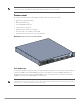
Chapitre 1 Contrôleur W-7200 Les contrôleurs Dell PowerConnect de la série W-7200 comprennent trois contrôleurs de réseau local sans fil d’entreprise. Ces contrôleurs connectent, contrôlent et intègrent les points d’accès sans fil et les points d’accès en modes moniteur (AM - Air monitor) dans un réseau local filaire. Modèles La série W-7200 comporte trois modèles qui offrent différents niveaux de fonctionnalité.
REMARQUE : des accessoires en option vendus séparément sont disponibles pour le contrôleur Dell PowerConnect W-7200. Contactez votre représentant Dell pour obtenir de plus amples informations et recevoir de l’aide.
Ports 10/100/1000Base-T (RJ-45) Le contrôleur W-7200 est équipé de deux ports cuivre 10/100/1000Base-T. La technologie Gigabit Ethernet fait appel aux huit brins et chaque paire est utilisée de façon bidirectionnelle, ce qui signifie que les mêmes paires sont utilisées pour la transmission et la réception des données. L’Illustration 2 illustre le brochage CAT-5 d’un connecteur RJ-45.
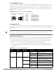
Tableau 5 Voyants des ports 1000Base-X Voyant Fonction Mode ACL Indicateur État LINK/ACT État de la liaison S/O Vert (fixe) Une liaison a été établie Vert (clignotant) Le port transmet ou reçoit des données Éteint Pas de liaison Administrative (Administratif) Vert (fixe) Port activé Éteint Port désactivé administrativement Duplex Vert (fixe) Duplex intégral Éteint Semi-duplex Vert (fixe) 1 Gbit/s Éteint Incompatibilité de vitesse État État du port Speed (Vitesse) Ports 10GBase
Voyants d’état et de gestion Outre les voyants de chaque port, le panneau avant comporte trois voyants supplémentaires qui indiquent l’état général du périphérique. Ces voyants donnent une indication visuelle générale de l’état du contrôleur W-7200.
L’afficheur ACL est utilisé au moyen des deux boutons de navigation situés à gauche de l’écran. z Bouton Menu : ce bouton permet de parcourir les menus de l’afficheur ACL. z Bouton Enter : ce bouton permet de valider et d’exécuter l’action présentée sur l’afficheur ACL. L’afficheur ACL dispose de quatre modes : z Boot (Démarrage) : ce mode permet d’afficher l’état de démarrage. z LED Mode (Mode Voyants) : ce mode permet d’afficher le mode actif des voyants d’état.
Tableau 12 Mode de l’afficheur ACL : Maintenance Fonctions/options du menu Affiche Upgrade Image (Mettre à jour l’image) Met à niveau l’image logicielle sur la partition sélectionnée à partir d’un emplacement prédéfini sur le périphérique flash USB connecté. Partition [0 | 1] Upgrade Image [no | yes] Upload Config (Télécharger la configuration) Charge la configuration actuelle du contrôleur à un emplacement prédéfini sur le périphérique flash USB connecté.
Connecteur de console mini-USB Le contrôleur W-7200 est équipé d’un connecteur mini-USB (type B) qui fournit un accès console pour un accès local direct. Si vous êtes connecté avec un connecteur mini-USB et le port console RJ-45, la connexion mini-USB est prioritaire. Pilote mini-USB Pour utiliser le port console mini-USB, vous devez installer le pilote mini-USB Dell sur l’ordinateur qui va gérer votre contrôleur W-7200. Les pilotes sont disponibles en téléchargement sur le site support.dell.com.
Interface USB Le contrôleur W-7200 dispose d’une interface USB 2.0. Il est possible d’utiliser un périphérique de stockage USB pour enregistrer et charger les configurations sur le contrôleur. Les fonctions USB sont contrôlées au moyen de l’afficheur ACL, situé sur le panneau avant du contrôleur. Pour plus d’informations sur l’afficheur ACL et ses fonctions, voir « Afficheur ACL » à la page 11. Connecteur d’extension Le connecteur d’extension est réservé à un usage ultérieur.
Module de ventilation ATTENTION : le contrôleur W-7200 est équipé d’un module de ventilation enfichable à chaud et pouvant être installé directement sur site. Chaque module de ventilation inclut quatre ventilateurs qui prennent l’air sur la partie avant du châssis et le font circuler vers l’arrière. Seuls trois ventilateurs sont nécessaires pour maintenir la température de fonctionnement du contrôleur, le quatrième étant prévu par souci de redondance.
Illustration 8 Schéma de circulation de l’air ATTENTION : alimentation ATTENTION : veillez à ne pas brancher ou débrancher le module alimentation lorsque le cordon d’alimentation est connecté. Vérifiez que le cordon est débranché du module d’alimentation avant d’installer ou de retirer ce dernier. Le module d’alimentation de la série W-7200 permet d’alimenter votre contrôleur W-7200.
Remplacement à chaud Le remplacement à chaud permet de remplacer l’un des modules d’alimentation défectueux en laissant les autres alimenter l’appareil normalement. Il est par conséquent inutile d’arrêter le contrôleur W-7200 pendant la procédure de remplacement. Le remplacement à chaud ne peut s’effectuer que si une solution d’alimentation redondante est en place.
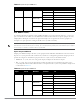
Voyants Chaque module d’alimentation dispose de trois voyants qui indiquent l’état du module. Tableau 16 Voyants du module d’alimentation Voyant Description Indicateur État c.a. État de l’alimentation provenant du secteur Vert (fixe) Fonctionnement normal Tension c.a. OK Rouge (fixe) Panne du module d’alimentation Vert (fixe) Fonctionnement normal Rouge (fixe) Panne du module d’alimentation Vert (fixe) Fonctionnement normal Rouge (fixe) Panne du module d’alimentation c.c.
| Contrôleur W-7200 Contrôleur Dell PowerConnect série W-7200 | Guide d’installation
Chapitre 2 Installation ATTENTION : l’installation du périphérique doit être réalisée par un technicien qualifié. Ce chapitre explique comment installer un contrôleur Dell PowerConnect W-7200 et choisir l’une des nombreuses options de montage. Le contrôleur W-7200 est livré avec un kit d’accessoires qui inclut l’équipement requis pour installer le contrôleur sur un rack telco de 19 po à deux points. D’autres options de montage peuvent être achetées séparément.
Sélection d’un emplacement Le contrôleur W-7200, comme tout autre périphérique réseau ou informatique, nécessite un environnement adapté aux composants électroniques. z Alimentation fiable. Assurez-vous que la prise électrique est compatible avec l’alimentation nominale du contrôleur W-7200. z Ventilation fraîche, sans condensation Pour fonctionner correctement, le contrôleur W-7200 nécessite une température ambiante comprise entre 0 et 40 ºC.
7200_08 Illustration 10 Supports de montage sur rack 4. Montez le contrôleur sur le rack de votre entreprise avec 4 (2 par support) vis cruciformes à tête plate M6 de 15 mm (voir Illustration 11). 7200_08a Illustration 11 Montage sur rack 5. Ménagez un espace minimum de 10 cm sur les côtés gauche et droit de l’unité pour assurer une bonne circulation de l’air et une ventilation adéquate.
Installation sur table ou étagère Outils et équipement requis z Pieds en caoutchouc (fournis) Instructions d’installation 1. Posez les pieds en caoutchouc sur le dessous du contrôleur. 2. Placez votre contrôleur à l’emplacement choisi. 3. Branchez le cordon d’alimentation secteur à l’arrière de l’unité. 4. Branchez l’autre extrémité du cordon d’alimentation sur une prise électrique pour alimenter le contrôleur.
Installation et retrait d’un module de ventilation REMARQUE : observez les précautions usuelles contre les décharges électromagnétiques lorsque vous installez ou retirez un module de ventilation. Le module de ventilation peut être remplacé sur site et sans arrêter le périphérique. Ceci permet d’intervenir sur le module de ventilation sans interrompre le fonctionnement du contrôleur W-7200. 1. Retirez l’ancien module de ventilation. a.
Installation et retrait d’un module d’alimentation ATTENTION : veillez à ne pas brancher ou débrancher le module d’alimentation lorsque le cordon d’alimentation est connecté. Vérifiez que le cordon est débranché du module d’alimentation avant d’installer ou de retirer ce dernier. REMARQUE : observez les précautions usuelles contre les décharges électromagnétiques lorsque vous installez ou retirez un module d’alimentation. Les modules d’alimentation sont remplaçables à chaud.
7200_07 Illustration 13 Installation d’un module d’alimentation 8. Branchez le cordon d’alimentation et assurez une connexion ferme avec la pince de fixation. Retrait d’un module d’alimentation Pour retirer un module d’alimentation du contrôleur W-7200 : 1. Soulevez la pince de fixation du cordon d’alimentation. 2. Débranchez le cordon du module d’alimentation. 3. À l’aide d’un tournevis cruciforme, desserrez la vis imperdable sur la partie avant du module d’alimentation. 4.
7200_09 Illustration 14 Installation d’un émetteur-récepteur enfichable à faible encombrement (SFP) Retrait d’un émetteur-récepteur enfichable à faible encombrement (SFP) Procédure de retrait d’un module SFP : 1. Ouvrez et déverrouillez le module SFP. 2. Retirez le module de son port en tirant dessus. Connexion d’un câble en fibre optique LC Procédure de connexion d’un câble LC en fibre optique sur un port SFP-SX ou SFP-LX : 1.
Chapitre 3 Spécifications, sécurité et conformité Spécifications du contrôleur W-7200 Spécifications physiques z z Dimensions du périphérique (sans les supports de montage) (H x L x P) Tous les modèles : 1,75 x 17,5 x 17,5 po Tous les modèles : 4,4 cm x 44,5 cm x 44,5 cm Poids du périphérique (avec un module d’alimentation installé) Tous les modèles : 7,45 kg Spécifications d’alimentation z Alimentation c.a. de 350 W Tension d’entrée c.a. : 100 à 240 V c.a. Courant d’entrée c.a.
Modèles réglementaires Ce document s’applique aux modèles suivants : Tableau 17 Numéros de modèles réglementaires Référence Numéro de modèle réglementaire W-7210 W-7210-IL ARCN0100 W-7210-US W-7220 W-7220-IL ARCN0101 W-7220-US W-7240 W-7240-IL ARCN0102 W-7240-US FCC Le présent périphérique est conforme à la section 15 des règles de la FCC.
Déclaration de conformité de l’Union européenne Ce produit porte la marque CE conformément à la directive européenne relative à la compatibilité électromagnétique (2004/108/CE). Aruba Networks Inc., déclare que les modèles 7210, 7220 et 7240 sont conformes aux exigences essentielles de la directive 2004/108/CE. La déclaration de conformité effectuée selon la directive 1999/5/CE peut être consultée aux emplacements suivants de l’Union européenne.
Procédure de mise au rebut des produits Dell Mise au rebut des équipements électriques et électroniques Les produits Dell en fin de vie utile font l’objet de pratiques de collecte et de traitement différentes dans les pays membres de l’UE, en Norvège et en Suisse ; ces produits portent donc le symbole illustré à gauche (poubelle barrée).