Dell PowerConnect W-7200 Serie Controller Installationsanleitung
Copyright © 2012 Aruba Networks, Inc. , Aruba Networks®, Aruba Wireless Networks®, das eingetragene „Aruba the Mobile Edge Company“-Logo und Aruba Mobility Management System® sind Marken von Aruba Networks. Dell™, das DELL™Logo und PowerConnect™ sind Marken von Dell Inc. Alle Rechte vorbehalten. Spezifikationen in diesem Handbuch können ohne Ankündigung geändert werden. Hergestellt in den USA. Alle andere Marken sind Eigentum der jeweiligen Inhaber.
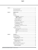
Inhalt Vorwort .......................................................................................................................................................................5 Übersicht über das Handbuch ......................................................................................................... 5 Verwandte Dokumentation ............................................................................................................... 5 Kontaktaufnahme mit dem Support......................
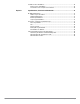
Installieren eines SFP-Moduls ....................................................................................................... 28 Entfernen eines SFP-Moduls.................................................................................................. 28 Anschließen eines faseroptischen LC-Kabels .................................................................... 29 Kapitel 3 Spezifikationen, Sicherheit und Konformität ...............................................................
Vorwort In diesem Dokument werden die Hardwaremerkmale des Controllers der Dell PowerConnect W-7200 Serie beschrieben. Es bietet eine ausführliche Übersicht über die physischen Merkmale und die Leistungsdaten eines jeden Controllermodells. Zudem wird in diesem Dokument beschrieben, wie Sie den Controller und seine Zubehörkomponenten installieren.
| Vorwort Dell PowerConnect W-7200 Serie Controller | Installationsanleitung
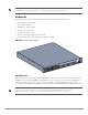
Kapitel 1 W-7200 Controller Die Dell PowerConnect W-7200 Serie von Controllern besteht aus drei WLAN-Controllern der EnterpriseKlasse. Diese Controller verbinden, steuern und integrieren auf intelligente Weise drahtlose Access Points (APs) und Air Monitors (AMs) in ein drahtgebundenes LAN-System. Modelle Die Serie W-7200 besteht aus drei Modellen mit unterschiedlichem Funktionsumfang.
HINWEIS: Optionales Zubehör zur Verwendung mit der Dell Power Connect W-7200 Serie kann separat erworben werden. Wenden Sie sich an Ihren Dell-Kundenbetreuer, um weitere Informationen und Beratung zu erhalten.
10/100/1000Base-T (RJ-45)-Ports Der W-7200 ist mit zwei 10/100/1000Base-T-Kupferports ausgestattet. Gigabit-Ethernet nutzt alle acht Leitungen und jedes Paar wird bidirektional verwendet, sodass dieselben Paare sowohl für die Datenübertragung als auch für den Empfang verwendet werden. Abbildung 2 zeigt die CAT-5-Pin-Belegung für einen RJ-45-Anschluss. Die CAT-5-Pin-Belegung fasst jeweils die folgenden Pins bei einem 10/100/1000Base-T-GigabitEthernet-Port zu Paaren zusammen: 1/2, 3/6, 4/5 und 7/8.
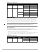
Tabelle 5 LEDs des 1000Base-X-Ports LED Funktion LCD-Modus Anzeige Status LINK/ACT Verbindungsstatus – Grün (kontinuierlich) Verbindung wurde hergestellt Grün (blinkend) Port sendet oder empfängt Daten Aus Keine Verbindung Grün (kontinuierlich) Schnittstelle aktiviert Aus Administration über die Schnittstelle deaktiviert Grün (kontinuierlich) Vollduplex Aus Halbduplex Grün (kontinuierlich) 1 Gbit/s Aus Ungleiche Geschwindigkeit Status Schnittstellenstatus Administrativ Duplex G
Tabelle 6 LEDs des 10GBase-X Ports LED Funktion LCD-Modus Anzeige Status Status Schnittstellenstatus Administrativ Grün (kontinuierlich) Schnittstelle aktiviert Aus Administration über die Schnittstelle deaktiviert Grün (kontinuierlich) Vollduplex Aus Halbduplex Grün (kontinuierlich) 10 Gbit/s Aus Ungleiche Geschwindigkeit Duplex Geschwindigkeit Management/Status-LEDs Zusätzlich zu den LEDs an den einzelnen Schnittstellen enthält die Vorderseite drei weitere LEDs, die den allgemeinen S
Abbildung 3 LCD 1 MENU R ENTE ER POW US STAT 2 3 ED PEER 7200_03 OLE CONS Tabelle 8 Komponenten des LCD-Bereichs Nr. Komponente Beschreibung 1 LCD-Bildschirm Zur Konfiguration des LCD-Verhaltens und anderer Basisvorgänge 2 Menütaste Zur Auswahl des LCD-Bildschirmmenüs 3 Eingabetaste Zum Ausführen von Aktionen auf dem LCD-Bildschirm Das LCD wird über die beiden Navigationstasten rechts neben dem Bildschirm bedient.
Tabelle 10 LCD-Modus: LED-Modus Funktion/Menüoptionen Anzeige Duplex LED-MODUS: DPX - zeigt den Duplexmodus der Schnittstelle an. Speed (Geschwindigkeit) LED-MODUS: SPD - zeigt die Geschwindigkeit der Schnittstelle an. Exit Idle Mode (Ruhemodus beenden) EXIT IDLE MENU (RUHEMODUS BEENDEN) Tabelle 11 LCD-Modus: Status Funktion/Menüoptionen Anzeige ArubaOS Version ArubaOS X.X.X.X PSU Status (Status des Netzteils) Zeigt den Status des Netzteils.
Deaktivieren des LCD-Bildschirms Standardmäßig ist der LCD-Bildschirm aktiviert. Wenn der W-7200 jedoch an einem Standort ohne physische Sicherheit bereitgestellt wird, kann der LCD-Bildschirm über die Befehlszeilenschnittstelle (CLI) deaktiviert werden. Beim Betätigen der Navigationstasten wird dann der Bildschirm beleuchtet und zeigt den Einschub, die Rolle, den Gerätenamen und ggf. Alarmmeldungen an. Außerdem ist es auch möglich, nur das Wartungsmenü anzuzeigen.
Konsolenschnittstelle (CONSOLE) Eine serielle Konsolenschnittstelle steht für den Anschluss an ein Terminal zur Verfügung, um die direkte lokale Verwaltung zu ermöglichen. An die RJ-45-Buchse kann ein serielles RS-232-Kabel mit Stecker angeschlossen werden.
Rückseite Die Rückseite des W-7200 Controller besteht aus den folgenden Komponenten: z Öffnungen für zwei Netzteile z Öffnung für einen Lüftereinschub z Erdungspunkt 7200_02 Abbildung 6 Rückseite Fan Tray (Lüftereinschub) VORSICHT: Der W-7200 ist mit einem Lüftereinschub ausgestattet, der vor Ort im laufenden Betrieb (Hot-Swapping) ausgetauscht werden kann. Jeder Lüftereinschub umfasst vier Einzellüfter, die Luft von der Vorderseite durch das Gehäuse zur Rückseite leiten.
Austausch im laufenden Betrieb (Hot-Swapping) Über das Hot-Swapping kann ein fehlerhafter Lüftereinschub ausgetauscht werden, ohne dass der W-7200 dabei ausgeschaltet werden muss. Abbildung 7 Fan Tray (Lüftereinschub) 2 3 1 Tabelle 14 Komponenten des Lüftereinschubs Nummer Komponente Beschreibung 1 Linke Verriegelung Zur Sicherung der linken Seite des Lüftereinschubs am Gehäuse. 2 Rechte Verriegelung Zur Sicherung der rechten Seite des Lüftereinschubs am Gehäuse. 3 Griff Zum Einsetzen bzw.
Abbildung 8 Luftstrom VORSICHT: Netzteil VORSICHT: Setzen Sie niemals ein Netzteil ein und entfernen Sie das Netzteil nicht, während das Netzkabel angeschlossen ist. Vergewissern Sie sich, dass das Netzkabel vom Netzteil getrennt wurde, bevor Sie das Netzteil einsetzen oder herausnehmen. Das Netzteil der W-7200 Serie bereitet die Stromversorgung für die Verwendung mit dem W-7200 auf.
Austausch im laufenden Betrieb (Hot-Swapping) Über das Hot-Swapping kann ein fehlerhaftes Netzteil ausgetauscht werden, während das Gerät von den anderen Netzteilen weiterhin mit Strom versorgt wird. Dies bietet den Vorteil, dass der W-7200 beim Austauschen des Netzteils nicht ausgeschaltet werden muss. Das Hot-Swapping wird nur unterstützt, wenn eine redundante Stromversorgung implementiert wurde.
LEDs Jedes Netzteil ist mit drei LEDs ausgestattet, über die Sie den Status des Netzteilmoduls überwachen können. Tabelle 16 LEDs des Netzteilmoduls LED Beschreibung Anzeige Status AC Netzstromstatus Grün (kontinuierlich) Normaler Betrieb Netzspannung ist OK.
Kapitel 2 Installation VORSICHT: Das Gerät darf nur von einem qualifizierten Techniker installiert werden. In diesem Kapitel wird beschrieben, wie der Dell PowerConnect W-7200 Controller mit einer der zahlreichen verfügbaren Montageoptionen installiert wird. Der W-7200 wird mit einem Zubehörkit geliefert, das alle Komponenten enthält, die für die Installation des Controller in einem standardmäßigen Zweipunkt-Telco-Rack (19 Zoll) benötigt werden. Weitere Montageoptionen sind separat erhältlich.
Auswählen eines Standorts Der W-7200 erfordert wie andere Netzwerk- und Computergeräte eine „elektrofreundliche“ Umgebung. z Zuverlässige Stromversorgung. Stellen Sie sicher, dass die verwendete Steckdose mit den Netzteilen des W-7200 kompatibel ist. z Kühle, nicht kondensierende Umgebung mit ausreichender Belüftung Für den ordnungsgemäßen Betrieb benötigt der W-7200 eine Umgebungstemperatur zwischen 0 und 40 ºC. Die Luftfeuchtigkeit muss im Bereich von 5 bis 95 % (nicht kondensierend) liegen.
Installationsschritte So installieren Sie einen Dell PowerConnect W-7200 Controller in einem Zweipunkt-Racksystem mit 48,26 cm/ 19 Zoll: 1. Halten Sie eine Rackmontagehalterung über die Montagelöcher auf einer Seite des Controllers (siehe Abbildung 10). 2. Befestigen Sie die Halterung mit vier M4 x 6 mm Kreuzschlitzschrauben und mithilfe eines passenden Schraubendrehers am Controller. 3. Wiederholen Sie diese Schritte auf der anderen Seite des Controllers. 7200_08 Abbildung 10 Rackmontagehalterungen 4.
5. Auf der rechten und linken Seite des Geräts müssen mindestens 10 cm Platz bleiben, um eine angemessene Belüftung zu gewährleisten. In Abbildung 8 auf Seite 18 finden Sie weitere Informationen zur erforderlichen Luftströmung für den W-7200. 6. An der Vorder- und Rückseite des Geräts muss zusätzlicher Platz frei bleiben, damit Stromkabel, Netzwerkkabel, LCD-Bereich und LED-Statusanzeigen frei zugänglich sind.
Einsetzen und Ausbauen eines Lüftereinschubs HINWEIS: Beachten Sie beim Installieren oder Entfernen von Lüftereinschüben relevante Sicherheitsmaßnahmen für die elektrostatische Entladung. Der Lüftereinschub kann vor Ort ausgetauscht werden und ist „hot-swapping-fähig“. Das bedeutet, dass Sie den Lüftereinschub austauschen können, ohne dass Sie den W-7200 ausschalten müssen. 1. Entfernen Sie den alten Lüftereinschub a.
Installieren und Ausbauen eines Netzteils VORSICHT: Setzen Sie niemals ein Netzteil ein und entfernen Sie das Netzteil nicht, während das Netzkabel angeschlossen ist. Vergewissern Sie sich, dass das Netzkabel vom Netzteil getrennt wurde, bevor Sie das Netzteil einsetzen oder herausnehmen. HINWEIS: Beachten Sie beim Installieren oder Entfernen von Netzteilmodulen relevante Sicherheitsmaßnahmen für die elektrostatische Entladung.
7200_07 Abbildung 13 Installieren eines Netzteils 8. Schließen Sie das Netzkabel an und sichern Sie es, in dem Sie den Haltebügel nach unten über das Netzkabel bewegen. Entfernen eines Netzteils So entfernen Sie ein Netzteil aus dem W-7200: 1. Heben Sie den Haltebügel vom Netzkabel an. 2. Ziehen Sie das Stromkabel vom Netzteilmodul ab. 3. Lösen Sie die klappbare unverlierbare Schraube an der Vorderseite des Netzteilmoduls mit einem Kreuzschlitzschraubendreher. 4.
Installieren eines SFP-Moduls HINWEIS: Beachten Sie beim Installieren oder Entfernen von SFP-Modulen relevante Sicherheitsmaßnahmen für die elektrostatische Entladung. So installieren Sie ein SFP-Modul im W-7200: 1. Schieben Sie das SFP-Modul mit der Oberseite nach oben in eine 1000Base-X-Schnittstelle, bis die Verbindung durch ein hörbares Klicken angezeigt wird. Weitere Informationen finden Sie unter Abbildung 14.
Anschließen eines faseroptischen LC-Kabels So schließen Sie ein faseroptisches LC-Kabel an ein SFP-SX- oder SFP-LX-Modul an: 1. Reinigen Sie den Stecker des faseroptischen Kabels, bevor Sie das Kabel in das SFP-Modul einstecken. 2. Stecken Sie das faseroptische Kabel in das SFP-Modul. Achten Sie darauf, dass die Verriegelung des Kabels zur Oberseite des SFP-Moduls zeigt. 3. Schieben Sie das Kabel in das Modul, bis die Verbindung durch ein hörbares Klicken angezeigt wird.
| Installation Dell PowerConnect W-7200 Serie Controller | Installationsanleitung
Kapitel 3 Spezifikationen, Sicherheit und Konformität W-7200 Spezifikationen Abmessungen und Gewicht z Geräteabmessungen ohne Montageklammern (HxBxT) z Alle Modelle: 4,4 x 44,5 x 44,5 cm Gerätegewicht (mit einem installierten Netzteil) Alle Modelle: 7,45 kg Netzteilspezifikationen z Netzteil mit 350 W Wechselstrom-Eingangsspannung: 100 V bis 240 V Wechselstrom AC Eingangsstrom: 5-2,5 A Wechselstrom-Eingangsfrequenz: 50-60 Hz Gewicht: 1,3 kg Betriebsspezifikationen z Temperatur b
Zulassungsmodelle Dieses Dokument gilt für die folgenden Modelle: Tabelle 17 Zulassungsmodellnummern Teilenummer Zulassungsmodellnummer W-7210 W-7210-IL ARCN0100 W-7210-US W-7220 W-7220-IL ARCN0101 W-7220-US W-7240 W-7240-IL ARCN0102 W-7240-US FCC Dieses Gerät erfüllt die Bedingungen von Abschnitt 15 der FCC-Bestimmungen.
EU-Regulierungskonformität Dieses Produkt trägt das CE-Kennzeichen in Übereinstimmung mit den Bestimmungen der EMV-Richtlinie (2004/108/EG) - CE. Aruba Networks Inc. erklärt hiermit, dass die Gerätemodelle 7210; 7220 & 7240 mit den wesentlichen Anforderungen und anderen relevanten Bestimmung der Richtlinie (2004/108/EC) konform sind. CE Die Konformitätserklärung gemäß Richtlinie 1995/5/EC kann unter folgender Adresse in der EU eingesehen werden.
Ordnungsgemäße Entsorgung von Dell-Geräten Verwertung von Elektro- und Elektronikaltgeräten Dell-Produkte müssen am Ende ihrer Standzeit in den Mitgliedsstaaten der EU, Norwegen und der Schweiz separat gesammelt und verwertet werden und sind daher durch das links abgebildete Symbol (durchgestrichene Mülltonne) gekennzeichnet.