Dell PowerConnect W-7200 Series Controller Installation Guide
Copyright © 2013 Aruba Networks, Inc. Aruba Networks trademarks include , Aruba Networks®, Aruba Wireless Networks®, the registered Aruba the Mobile Edge Company logo, and Aruba Mobility Management System®. Dell™, the DELL™ logo, and PowerConnect™ are trademarks of Dell Inc. All rights reserved. Specifications in this manual are subject to change without notice. Originated in the USA. All other trademarks are the property of their respective owners.
Contents Preface.......................................................................................................................................................................5 Guide Overview................................................................................................................................... 5 Related Documentation..................................................................................................................... 5 Contacting Support ..................
Removing a Power Supply ...................................................................................................... 27 Installing an SFP ............................................................................................................................... 27 Removing an SFP...................................................................................................................... 27 Connecting an LC Fiber Optic Cable..............................................................
Preface This document describes the hardware features of the Dell PowerConnect W-7200 Series Controller. It provides a detailed overview of the physical and performance characteristics of each controller model and explains how to install the controller and its accessories. Guide Overview Chapter 1, “Dell PowerConnect W-7200 Controller” on page 7 provides a detailed hardware overview of the W-7200 controller and each of its components.
This page is intentionally left blank.
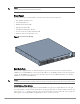
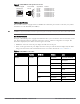
Chapter 1 Dell PowerConnect W-7200 Controller The Dell PowerConnect W-7200 series of controllers consists of three enterprise-class, wireless LAN controllers. These controllers connect, control, and intelligently integrate wireless Access Points (APs) and Air Monitors (AMs) into a wired LAN system. Models The Dell PowerConnect W-7200 series controller includes three models that provide varying levels of functionality.
NOTE: Optional accessories are available for use with the Dell PowerConnect W-7200 Series and are sold separately. Contact your Dell sales representative for details and assistance.
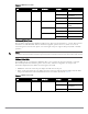
Figure 2 10/100/1000Base-T Management Port Pin Out 1000Base-T Gigabit Ethernet Port RJ-45 Female Pin-Out 1 2 3 4 5 6 7 8 Signal Name Function BI_DA+ BI_DABI_DB+ BI_DC+ BI_DCBI_DBBI_DD+ BI_DD- Bi-directional pair +A Bi-directional pair -A Bi-directional pair +B Bi-directional pair +C Bi-directional pair -C Bi-directional pair -B Bi-directional pair +D Bi-directional pair -D 1000Base-X (SFP) Ports The W-7200 controller is equipped with two 1000Base-X combination ports for fiber connectivity only and are
Table 5 1000Base-X Port LEDs LED Function LCD Mode Indicator Status LINK/ACT Link status N/A Green (Solid) Link has been established Green (Blinking) Port is transmitting or receiving data Off No link Green (Solid) Port Enabled Off Port Administratively Disabled Green (Solid) Full-duplex Off Half-duplex Green (Solid) 1 Gbps Off Speed mismatch Status Port status Administrative Duplex Speed 10GBase-X (SFP+) Ports The W-7200 is equipped with 4 10GBase-X (SFP+) ports.
Table 6 10GBase-X Port LEDs LED Function LCD Mode Indicator Status Status Port status Administrative Green (Solid) Port Enabled Off Port Administratively Disabled Green (Solid) Full-duplex Off Half-duplex Green (Solid) 10 Gbps Off Speed mismatch Duplex Speed Management/Status LED Indicators In addition to the LEDs on each individual port, there are three additional LEDs on the front panel that provide overall status of the device.
Figure 3 LCD Panel 1 MENU R ENTE ER POW US STAT 2 3 ED PEER 7200_03 OLE CONS Table 8 LCD Panel Components Callout Component Description 1 LCD Screen Used to configure LCD behavior and other basic operations 2 Menu Button Used to select the LCD screen menu 3 Enter Button Used to execute actions on the LCD Screen The LCD panel is operated using the two navigation buttons to the left of the screen. Menu: Allows you to navigate through the menus of the LCD panel.
Table 10 LCD Panel Mode: LED Mode Function/Menu Options Displays Speed LED MODE: SPD - displays the speed of the port. Exit Idle Mode EXIT IDLE MENU Table 11 LCD Panel Mode: Status Function/Menu Options Displays ArubaOS Version ArubaOS X.X.X.X PSU Status Displays status of the power supply unit. PSU 0: [OK | FAILED | MISSING] PSU 1: [OK | FAILED | MISSING] Fan Tray Displays fan tray status.
To disable the LCD screen, enter the Enable mode and use the following CLI commands: (host) #configure terminal (host) (config) #lcd-menu (host) (lcd-menu) #disable menu To disable only the Maintenance menu or one of its sub-menus, enter the Enable mode and use the following CLI commands: (host) #configure terminal (host) (config) #lcd (host) (lcd-menu) #disable menu maintenance ? factory-default halt-system media-eject reload-system upgrade-image upload-config (host) (lcd-menu) #disable menu maintenance u
Serial Console Port Adaptor A modular adaptor can be used to convert the RJ-45 (female) connector to a DB9 (male) connector. Refer to Figure 5 for complete details. Figure 5 RJ-45 (female) to DB9 (male) Modular Adaptor Conversion RJ-45 Female Pin-Out 1 2 3 TxD 4 5 GND 6 RxD 7 8 Internal Connections RJ-45 TxD 3 4 5 GND RxD 6 DB-9 Male Pin-Out DB-9 2 5 3 5 4 3 2 1 9 8 7 6 Ground RxD TxD USB Interface The W-7200 controller is equipped with one USB 2.0 interface.
Fan Tray CAUTION: The W-7200 controller is equipped with a field-replaceable, hot-swappable fan tray. Each fan tray features four individual fans that pull air through the chassis from the front through to the rear. Each fan tray can tolerate the failure of a single fan while maintaining a safe operating temperature for the controller CAUTION: The W-7200 controller is not compatible with fan trays from other Dell hardware platforms.
Figure 8 Air Flow Pattern Power Supply CAUTION: Never insert or remove a power supply while the power cord is connected. Verify that cord has been disconnected from the power supply before installation or removal. The W-7200 series controller’s Power Supply adapts electrical power for use with the W-7200. The chassis has two slots that can hold individual power supplies to support load sharing, redundancy, and fault tolerance. The W-7200 controller comes equipped with a single 350W AC power supply.
Modules The 350W power supply is an autosensing, load-sharing, redundant power supply module that supports an input voltage of 100 VAC to 240 VAC. Each power supply has a country-specific power cord for connection to an AC power outlet. Figure 9 Power Supply (AC Power Supply Shown) 1 2 3 7200_06 4 7 8 5 6 Table 15 Power Supply Components Callout Component Description 1 Latch Used to secure the power supply to the chassis. 2 AC LED AC status LED. 3 DC LED DC status LED.
Table 16 Power Supply Module LEDs LED Description Indicator Status DC DC Status Green (Solid) Operating Normally Red (Solid) Power Supply Failure Green (Solid) Operating Normally Red (Solid) Power Supply Failure TEMP Power Supply Temperature Dell PowerConnect W-7200 Series Controller | Installation Guide Dell PowerConnect W-7200 Controller | 19
This page is intentionally left blank.
Chapter 2 Installation CAUTION: Installation of the device should be performed by a trained installation professional. This chapter describes how to install a Dell PowerConnect W-7200 controller using the many mounting options available. The W-7200 controller ships with an accessory kit that includes the equipment needed to install the controller in standard, two-point 19-inch telco rack. Additional mounting options are sold separately.
Modules must be kept in anti-static packaging when not installed in the chassis. Do not ship/store this product near strong electro-magnetic, electrostatic, magnetic or radioactive fields. Do not disassemble the chassis or any module. Selecting a Location The W-7200 controller, like other network and computing devices, requires an “electronics friendly” environment. Reliable power. Verify that your electrical outlet is compatible with the W-7200 power supplies.
3. Repeat these steps on the opposite side of the controller. 7200_08 Figure 10 Rack Mount Brackets 4. Mount the controller within your organization’s rack system using four (two per bracket) M6 x 15mm phillips flat head screws and suitable screwdriver (see Figure 11). 7200_08a Figure 11 Rack Mount Installation 5. Leave a minimum of four inches (10cm) of space on the left and right side of the unit for proper air flow and ventilation.
6. Leave additional space in front and back of the unit to access power cords, network cables, the LCD panel, and LED status indicators Table or Shelf Installation Required Tools and Equipment Rubber Feet (included) Installation Steps 1. Attach the included rubber feet to the bottom of the controller. 2. Place your controller in the location you have chosen. 3. Connect the AC power cord to the rear of the unit. 4.
2. Align the new fan tray module with opening in the controller, as shown in Figure 12. CAUTION: Ensure that fan tray module is correctly aligned with the opening on the W-7200. Failure to do so can result in damage to the fan tray module. 3. Pull down the hinged captive screws on the new fan tray module and align its tabs with the slots on either side of the opening. 4. Slide the fan tray module into the controller. 5.
Installing and Removing a Power Supply CAUTION: Never insert or remove a power supply while the power cord is connected. Verify that cord has been disconnected from the power supply before installation or removal. NOTE: Use standard ESD precautions when installing or removing a power supply module. The power supply modules are hot-swappable. Hot swapping allows you to replace a failed power supply without powering down the W-7200 controller during the replacement process.
Removing a Power Supply To remove a power supply from your W-7200 controller: 1. Lift the power cord retaining clip from the power cord. 2. Remove the power cable connected to the power supply module. 3. Using a Phillips head screwdriver, loosen the hinged captive screw on the front of the power supply module. 4. Lower the hinged captive screw as far as it can go. 5. Using the power supply module’s handle, pull the module out. 6.
2. Insert the fiber optic cable into the SFP module. Ensure that the latch on the cable faces the top of the SFP module. 3. Slide the cable into place until a connection is made and an audible click is heard. To disconnect an LC fiber optic cable from an SFP-SX or SFP-LX module: 1. Depress the transceiver handle to release the latch on the cable and simultaneously pull the cable out of the port.
Chapter 3 Specifications, Safety, and Compliance W-7200 Controller Specifications Physical Device Dimensions (without mounting brackets) (HxWxD) All Models: 1.75” x 17.5” x 17.5” All Models: 4.4 cm x 44.5 cm x 44.5 cm Device Weight (with one AC power supply installed) All Models: 16.43 lbs (7.45 kg) Power Supply Specifications 350W AC Power Supply AC Input Voltage: 100 VAC to 240 VAC AC Input Current: 5-2.5A AC Input Frequency: 50 - 60 Hz Weight: 2.8 lbs (1.
Regulatory Models This document covers the following models: Table 17 Regulatory Model Numbers Part Number Regulatory Model Number W-7210 W-7210-IL ARCN0100 W-7210-US W-7220 W-7220-IL ARCN0101 W-7220-US W-7240 W-7240-IL ARCN0102 W-7240-US FCC This device complies with Part 15 of the FCC Rules. Operation is subject to the following two conditions: 1. this device may not cause harmful interference 2.
EU Regulatory Conformance This product is CE marked according to the provisions of the EMC Directive (2004/108/EC) - CE. Dell, hereby declares that 7210; 7220 & 7240 device models are in compliance with the essential requirements and other relevant provisions of Directive (2004/108/EC). CE The Declaration of Conformity made under Directive 1999/5/EC is available for viewing at the following location in the EU community.
China RoHS Dell products also comply with China environmental declaration requirements and are labeled with the “EFUP 50” label shown at the left.