Dell PowerConnect WAirWave 7.
Copyright © 2011 Aruba Networks, Inc. Aruba Networks trademarks include , Aruba Networks®, Aruba Wireless Networks®, the registered Aruba the Mobile Edge Company logo, and Aruba Mobility Management System®. Dell™, the DELL™ logo, and PowerConnect™ are trademarks of Dell Inc. All rights reserved. Specifications in this manual are subject to change without notice. Originated in the USA. All other trademarks are the property of their respective owners.
Contents Preface.......................................................................................................................................................................5 Document Organization..................................................................................................................... 5 Note, Caution, and Warning Icons .................................................................................................. 6 Contacting Support ................................
Understanding WMS Offload Impact on Dell PowerConnect W-Series infrastructure....... 26 Chapter 6 Dell PowerConnect W-Specific Capabilities in AMP ..................................................29 Dell PowerConnect W Traps for RADIUS Auth & IDS Tracking............................................... 29 Remote AP Monitoring .................................................................................................................... 30 ARM & Channel Utilization Information.........................
Preface This preface provides an overview of this best practices guide and contact information for Dell, and includes the following sections: “Document Organization” on page 5 “Note, Caution, and Warning Icons” on page 6 “Contacting Support” on page 6 Document Organization This best practices guide includes instructions and examples of optimal ways to use and integrate the AirWave Management Platform (AMP) with Dell PowerConnect W-Series devices and infrastructure.
Note, Caution, and Warning Icons This document uses the following note, caution, and warning icons to emphasize advisories for certain actions, configurations, or concepts: NOTE: Indicates helpful suggestions, pertinent information, and important things to remember. CAUTION: Indicates a risk of damage to your hardware or loss of data. WARNING: Indicates a risk of personal injury or death. Contacting Support Table 2 Website contact Web Site 6 | Preface Main Website dell.com Support Website support.
Chapter 1 Overview This document provides best practices for leveraging Dell PowerConnect W-AirWave (AMP, Master Console and Failover) to monitor and manage your Dell PowerConnect W-Series infrastructure. Dell PowerConnect WSeries wireless infrastructure provides a wealth of functionality such as firewall, VPN, remote AP, IDS, IPS, and ARM, as well as an abundance of statistical information.
| Overview Dell PowerConnect W-AirWave | Version 7.
Chapter 2 Configuring AirWave for Global Dell PowerConnect W-Series Infrastructure This chapter explains how to optimally configure Dell PowerConnect W-AirWave to globally manage your Dell PowerConnect W-Series infrastructure, and contains the following topics: “Disabling Rate Limiting in AMP Setup > General” on page 9 “Entering Credentials in Device Setup > Communication” on page 9 “Setting Up Recommended Timeout and Retries” on page 10 “Setting Up Time Synchronization” on page 11 “Enab
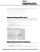
3. Enter the SNMP Community String. NOTE: Be sure to note the community string, because it must match the SNMP Trap community string which is configured later in this document. Figure 2 Dell PowerConnect W Credentials in Device Setup > Communication 4. Enter the required fields for configuration and basic monitoring: Telnet/SSH Username Telnet/SSH Password “enable” Password 5.
Setting Up Time Synchronization Setting up NTP on AirWave On the AMP Setup > Network page, locate the Network Time Protocol (NTP) section. The Network Time Protocol is used to synchronize the time between AMP and your network reference NTP server. NTP servers synchronize with external reference time sources, such as satellites, radios, or modems. NOTE: Specifying NTP servers is optional. NTP servers synchronize the time on the AMP server, not on individual access points.
AirWave Setup Follow these steps in AMP: 1. Navigate to AMP Setup > General. 2. In the Additional AMP Services section, set Enable AMON Data Collection to Yes, as shown in Figure 4: Figure 4 AMON Data Collection setting in AMP Setup > General 3. Select Save. Controller Setup (Master & Local) CAUTION: Enabling these commands on AOS versions prior to 6.0.1.0 can result in performance issues on the controller. If you are running previous firmware versions such as AOS 6.0.0.0, you should upgrade to AOS 6.0.
Chapter 3 Configuring a Dell PowerConnect W Group in AMP It is prudent to establish a Dell PowerConnect W Group within AMP. During the discovery process you will move new discovered controllers into this group. This chapter contains the following topics: “Basic Monitoring Configuration” on page 13 “Advanced Configuration” on page 14 Basic Monitoring Configuration 1. Navigate to Groups > List. 2. Select Add. 3.
Figure 6 Group SNMP Version for Monitoring 12. Select Save and Apply. Advanced Configuration Refer to the Dell PowerConnect W AirWave Configuration Guide located at support.dell.com/manuals for detailed instructions. 14 | Configuring a Dell PowerConnect W Group in AMP Dell PowerConnect W-AirWave | Version 7.
Chapter 4 Discovering Dell PowerConnect WSeries Infrastructure This chapter guides you through the process of discovering and managing your Dell PowerConnect W-Series infrastructure. AMP utilizes Dell PowerConnect W-Series topology to efficiently discover downstream infrastructure.
Figure 7 Dell PowerConnect W Credentials in Device Setup > Add 4. Enter the required fields for configuration and basic monitoring: Telnet/SSH Username Telnet/SSH password “enable” password 5. Enter the required fields for WMS Offload SNMPv3 Auth Protocol SNMPv3 Privacy Protocol SNMPv3 Username Auth Password Privacy Password NOTE: The protocols should be SHA and DES in order for WMS Offload to work.
CAUTION: If you are using SNMPv3 and the controller's date/time is incorrect, the SNMP agent will not respond to SNMP requests from AMP SNMP manager. This will result in the controller and all of its downstream access points showing as Down in AMP. 6. Assign controller to a Group & Folder. 7. Ensure Monitor Only option is selected. 8. Select Add. 9. Navigate to APs/Devices > New page. 10. Select the Dell PowerConnect W Master controller you just added from the list of new devices. 11.
| Discovering Dell PowerConnect W-Series Infrastructure Dell PowerConnect W-AirWave | Version 7.
Chapter 5 AMP and Dell PowerConnect W-Series Integration Strategies This chapter describes strategies for integrating AMP and Dell PowerConnect W-Series, and contains the following topics: “Integration Goals” on page 19 “Example Use Cases” on page 20 “Prerequisites for Integration” on page 21 “Enable Stats Utilizing AMP” on page 21 “WMS Offload Utilizing AMP” on page 22 “Define AMP as Trap Host using ArubaOS CLI” on page 22 “Understanding WMS Offload Impact on Dell PowerConnect W
Example Use Cases The following are example use cases of integration strategies: When to Use Enable Stats You want to pilot Dell PowerConnect W-AirWave and doesn't want to make major configuration changes to their infrastructure or manage configuration from AMP. NOTE: Enable Stats still pushes a small subset of commands to the controllers via SSH. See “Enable Stats Utilizing AMP” on page 21.
Prerequisites for Integration If you have not discovered the Dell PowerConnect W-Series infrastructure or configured credentials, refer to the previous chapters of this book: Chapter 2, “Configuring AirWave for Global Dell PowerConnect W-Series Infrastructure” on page 9 Chapter 3, “Configuring a Dell PowerConnect W Group in AMP” on page 13 Chapter 4, “Discovering Dell PowerConnect W-Series Infrastructure” on page 15 Enable Stats Utilizing AMP To enable stats on the Dell PowerConnect W-series con
audit these setting (display mismatches) and you will need to apply to the controller by hand. See Appendix A, “CLI ArubaOS & AMP Commands” on page 37 for detailed instructions.
(Controller-Name) (config) # snmp-server host version 2c NOTE: Ensure the SNMP community matches those that were configured in Chapter 2, “Configuring AirWave for Global Dell PowerConnect W-Series Infrastructure” . (Controller-Name) (config) # snmp-server trap source (Controller-Name) (config) # write mem CAUTION: Do not configure the SNMP version to v3 because AMP does not support SNMPv3 traps/informs.
wlsxFrameReceiveErrorRateExceeded wlsxFrameFragmentationRateExceeded wlsxFrameBandWidthRateExceeded wlsxFrameLowSpeedRateExceeded wlsxFrameNonUnicastRateExceeded wlsxChannelRateAnomaly wlsxNodeRateAnomalyAP wlsxNodeRateAnomalySta wlsxEAPRateAnomaly wlsxSignalAnomaly wlsxSequenceNumberAnomalyAP wlsxSequenceNumberAnomalySta wlsxApFloodAttack wlsxInvalidMacOUIAP wlsxInvalidMacOUISta wlsxStaRepeatWEPIVViolation wlsxStaWeakWEPIVViolation wlsx
Figure 10 Verify IP Address on APs/Devices > Monitor Page Verify that there is a SNMPv2 community string that matches the SNMP Trap community string on the controller. (Controller-Name) # show snmp community SNMP COMMUNITIES ---------------COMMUNITY ACCESS VERSION --------- -----------public READ_ONLY V1, V2c (Controller-Name) # #show snmp trap-host SNMP TRAP HOSTS --------------HOST VERSION ---------10.2.32.
Understanding WMS Offload Impact on Dell PowerConnect W-Series infrastructure When offloading WMS, it is important to understand what functionality is migrated to AMP and what functionality is deprecated. The following ArubaOS tabs and sections are deprecated after offloading WMS: Plan Tab - where floor plans are stored and heatmaps are generated. Prior to offloading WMS, ensure that you have exported floor plans from ArubaOS and imported into AMP.
Known Interfering APs - partial data is available in AMP on each APs/Devices > Manage page Router Summary Routers Detected - no summary data available in AMP Client Classification Summary Valid Clients - summary data available on all pages in the dashboard Interfering clients - no summary data available in AMP Disabled Clients - no summary data available in AMP See “Rogue Device Classification” on page 33 for more information on security, IDS, WIPS, WIDS, classification, and RAPIDS.
| AMP and Dell PowerConnect W-Series Integration Strategies Dell PowerConnect W-AirWave | Version 7.
Chapter 6 Dell PowerConnect W-Specific Capabilities in AMP This chapter discusses Dell PowerConnect W-specific capabilities in AMP, and contains the following topics: “Dell PowerConnect W Traps for RADIUS Auth & IDS Tracking” on page 29 “Remote AP Monitoring” on page 30 “ARM & Channel Utilization Information” on page 30 “Viewing Controller License Information” on page 32 “Rogue Device Classification” on page 33 “Rules-Based Controller Classification” on page 34 Dell PowerConnect W T
Remote AP Monitoring To monitor remote APs, follow these steps: 1. From the APs/Devices > List page, filter on the Remote Device column to find remote devices. 2. To view detailed information on the remote device, select the device name. The page illustrated in Figure 14 appears. Figure 14 Remote AP Detail Page 3. You can also see if there are users plugged into the wired interfaces in the Connected Users list. NOTE: This feature is only available when the remote APs are in split tunnel and tunnel modes.
See the Dell PowerConnect W-AirWave 7.3 User Guide in Home > Documentation for more information on the data displayed in the Radio Statistics page for these devices. VisualRF and Channel Utilization To view how channel utilization is impacting an area within a building, follow these steps: 1. Navigate to a floor plan by clicking on the thumbnail on a device’s APs/Devices > Monitor page or navigating to VisualRF > Floor Plans page. 2. Select the Overlays menu. 3. Select Utilization overlay. 4.
3. Enter the duration evaluation period. 4. Select Add New Trigger Condition. 5. Create a trigger condition for Radio Type and select the frequency to evaluate. 6. Select total, receive, transmit, or interference trigger condition. 7. Set up any restrictions or notifications (refer to the Dell PowerConnect W-AirWave 7.3 User Guide in Home > Documentation for more details) 8. When finished, select Add. Viewing Channel Utilization Alerts 1. Navigate to APs/Devices > Monitor or System > Alerts. 2.
Rogue Device Classification Only complete this section if you have completed WMS Offload procedure above. After offloading WMS, AMP maintains the primary ARM, WIPS, and WIDS state classification for all devices discovered over-the-air.
To update a group of devices' controller classification to match the AOS device classification, navigate to RAPIDS > List and utilize the Modify Devices checkbox combined with the multiple sorting a filtering features. Table 6 ARM to AMP Classification Matrix AMP ArubaOS (ARM) Unclassified (default state) Unknown Valid Valid Contained DOS 1. Navigate to the Users > User Detail page for the user. 2.
Figure 22 Using Controller Classification Changing RAPIDS based on Controller Classification 1. Navigate to RAPIDS > Rules. 2. In the Classification drop-down menu, select desired RAPIDS classification. 3. Select Controller Classification from drop-down menu, as shown in Figure 23. Figure 23 Configure Rules for Classification 4. Select Add. 5. Select desired controller classification to use as an evaluation in RAPIDS. 6. Select Save.
| Dell PowerConnect W-Specific Capabilities in AMP Dell PowerConnect W-AirWave | Version 7.
Appendix A CLI ArubaOS & AMP Commands Enable Channel Utilization Events Utilizing ArubaOS CLI (Local and Master Controllers) CAUTION: Enabling these commands on ArubaOS versions prior to 6.1 can result in performance issues on the controller. SSH into the controller, and enter “enable” mode, and issue the following commands: (Controller-Name) # configure terminal Enter Configuration commands, one per line.
Offload WMS Utilizing ArubaOS CLI and AMP CLI (SNMP Walk) NOTE: Do not use these commands if using AMP GUI. ArubaOS CLI SSH into all controllers (local and master), and enter “enable” mode, and issue the following commands: (Controller-Name) # configure terminal Enter Configuration commands, one per line.
Ensuring Master Controller Pushes Config to Local Controllers Utilizing ArubaOS CLI NOTE: Do not use these commands if using AMP GUI. (Controller-Name) (config) # cfgm mms config disable NOTE: This command ensures configuration changes made on the master controller will propagate to all local controllers. (Controller-Name) (config) # write mem Disable Debugging Utilizing ArubaOS CLI If you are experiencing performance issues on the Master Controller, ensure that debugging is disabled.
Copy & Paste to Enable Proper Traps With the ArubaOS CLI To ensure the proper traps are configured on Dell PowerConnect W-series controllers copy and paste the following command after entering “enable” mode and issuing the configure terminal command: snmp-server snmp-server snmp-server snmp-server snmp-server snmp-server snmp-server snmp-server snmp-server snmp-server snmp-server snmp-server snmp-server snmp-server snmp-server snmp-server snmp-server snmp-server snmp-server snmp-server snmp-server snmp-serv
Appendix B How AMP Acquires Data from Dell PowerConnect W-Series devices Table 7 How AMP Acquires Data from Dell PowerConnect W-Series devices Data Elements Controller/Thin AP SNMP MIB SNMP Traps AMON CLI/SSH WMS Offload RTLS Configuration interface Device configuration/audit X User and client interfaces Assoc/auth/roam X Bandwidth X Signal quality X Auth failures X X X AP/radio interfaces CPU & memory utilization <--------------------------------N/A-------------------------------------
| How AMP Acquires Data from Dell PowerConnect W-Series devices Dell PowerConnect W-AirWave | Version 7.
Appendix C WMS Offload Details WMS Offload instructs the Master controller to stop correlating ARM, WIPS, and WIDS state information amongst its Local controllers, because AMP will assume this responsibility. Figure 24 depicts how Dell PowerConnect W-AirWave communicates state information with Local controllers. Figure 24 ARM/WIPS/WIDS Classification Message Workflow State Correlation Process 1. Dell PowerConnect W-Series AP hears rogue device A 2.
7. AMP periodically polls each Local controller's MIB to ensure state parity with the AMP database. If the Local controller's device state does not comply with the AMP database, AMP will send a re-classification message to bring it back into compliance. NOTE: The Rogue Detail page displays a BSSID table for each rogue that displays the desired classification and the classification on the device.
Appendix D Increasing Location Accuracy Understand Band Steering's Impact on Location Band steering can negatively impact location accuracy when testing in highly mobile environment. The biggest hurdle is scanning times in 5 GHz frequency. Table 8 Location accuracy impact Operating Frequency Total Channels Scanning Frequency Scanning Time Total Time One Pass 2.4 GHz 11 (US) 10 seconds 110 milliseconds 121.21 seconds 5 GHz 24 (US) 10 seconds 110 milliseconds 242.
Figure 26 Typical Tag Deployment Prerequisites You will need the following information to monitor and manage your Dell PowerConnect W-Series infrastructure.
Enable RTLS on Controller NOTE: RTLS can only be enabled on the master controller and it will automatically propagate to all local controllers. SSH into master controller, enter “enable” mode, and issue the following commands: (Controller-Name) # configure terminal Enter Configuration commands, one per line.
Ensure chirps are published to Airbus by snooping on proper topics [root@AMP server]# airbus_snoop rtls_tag_report Snooping on rtls_tag_report: Mon Oct 20 13:49:03 2008 (1224535743.