Getting Started Guide Dell Networking W-AirWave 8.
Copyright © 2014 Aruba Networks, Inc. Aruba Networks trademarks include , Aruba Networks®, Aruba ® Wireless Networks , the registered Aruba the Mobile Edge Company logo, and Aruba Mobility Management System®. Dell™, the DELL™ logo, and PowerConnect™ are trademarks of Dell Inc. All rights reserved. Specifications in this manual are subject to change without notice. Originated in the USA. All other trademarks are the property of their respective owners.
Contents Overview Initial Setup How Do I Add Devices? Adding Devices with the Device Setup > Add Page Discovering New Devices Configuring and Running a Scan Set Add Newly Discovered Devices to a Group Auditing Device Configuration Adding Multiple Devices from a File Adding Universal Devices Adding a Dell Controller Adding as a Management Server Adding as a Trap Host How are Folders and Groups Organized? Groups Folders How Do I Define New Users and Roles? How Do I Define Credentials for Devices that Communi
Device Reports Client Reports Network Reports Security Reports Custom Reports 22 22 22 23 23 Monitoring Practices 25 Viewing Device Monitoring Statistics Monitoring Data for Wired Devices (Routers and Switches) Understanding the APs/Devices > Monitor Pages for all Device Types Understanding the APs/Devices > Interfaces Page Monitoring with the RF Performance Page Viewing Syslog Messages 4 | Contents 25 26 26 27 28 29 Dell Networking W-AirWave 8.
Chapter 1 Overview Congratulations on successfully installing Dell Networking W-AirWave 8.0! So where do you go from here? This document is designed to help you with your initial setup. It also provides information on common configuration options and daily monitoring practices. Refer to the following sections: l "Initial Setup" on page 5 l "Common Configuration Options" on page 17 l "Monitoring Practices" on page 25 Initial Setup Dell Networking W-AirWave 8.
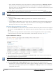
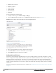
Figure 1: Device Setup > Add Page Illustration 2. Select Add. The Device Communications and Location sections appear (see Figure 2). Figure 2: Device Setup > Add > Device Communications and Location Sections 3. Complete the Device Communications and Location settings for the new device. Settings can differ from device to device based on the type of device and the features that the device supports.
If you select Manage read/write, AirWave overwrites existing device settings with the Groups settings. Place newly discovered devices in Monitor read/only mode to enable auditing of actual settings instead of Group Policy settings. 6. Select Add to finish manually adding devices to the network. Discovering New Devices In addition to manually adding devices, devices connected to your network can automatically be discovered and added. AirWave performs device discovery using the following methods.
c. In the Automatic Authorization section, select whether to override the global setting in AMP Setup > General and have New Devices be automatically authorized into the New Device List, the same Group/Folder as the discovering devices, the same Group/Folder as the closest IP neighbor, or a specified auto-authorization group and folder. Be sure to note this location. d. Select Add when you are finished, and repeat these steps for each scan set that you want to create.
l In Manage Read/Write mode, AirWave compares the device's current configuration settings with the Group configuration settings and automatically updates the new device's configuration to match the Group policy. Put devices in Monitory Only + Firmware Upgrades mode when they are added to a newly established device group. This avoids overwriting any important existing configuration settings. 5. Click Add.
l SNMPv3 Privacy Protocol l SNMPv3 Username l Telnet Username l Telnet Password l Enable Password l SNMP Port You can download and customize a file. 1. To import a CSV file, go to the Device Setup > Add page. 2. Click the Import Devices via CSV link. The Upload a list of devices page displays. See Figure 4. Figure 4: Device Setup > Add > Import Devices via CSV Page Illustration 3. Select a group and folder into which to import the list of devices. 4.
AirWave collects basic information about universal devices including name, contact, uptime and location. After you add a universal device, you can view a list of its interfaces on APs/Devices > Manage. Select the pencil icon next to an interface, to select to be non-monitored or monitored as an interface. AirWave collects this information and displays it on the APs/Devices > Monitor page in the Interface section. AirWave supports MIB-II interfaces and polls in/out byte counts for up to two interfaces.
You can add up to four addresses. Adding as a Trap Host To ensure the AirWave server is defined as a trap host, access the command line interface of each controller (master and local), enter enable mode, and issue the following commands: (Controller-Name) # configure terminal Enter Configuration commands, one per line.
l Security settings - VLANs, WEP, 802.1x, ACLs, and so forth l Radio settings - data rates, fragmentation threshold, RTS threshold, DTIM, preamble, and so forth. When configuration changes are applied at a group level, they are assigned automatically to every device within that group. These changes must be applied to every device while in Managed mode. When you first configure AirWave, only a group named Access Points is available.
How Do I Define Credentials for Devices that Communicate with AirWave? On the Device Setup > Communication page, you can configure AirWave to communicate with your vendor-specific devices, and you can set SNMP polling information. The configuration defines the default credentials for future devices; it does not impact existing devices. See Figure 5.
l If you select Do Not Modify SNMP Settings, then AirWave will not modify any SNMP settings. If SNMP is not already initialized on the Symbol, Nomadix, and Cisco IOS APs, AirWave is not able to manage them. l If you select Enable read-write SNMP, then AirWave can manage networks with Symbol, Nomadix, Cisco IOS AP that do not have SNMP initialized. I Have a Mismatch. What Do I Do? AirWave has a configuration policy and a mismatch is a device that does not match the configuration that AirWave wants.
| Overview Dell Networking W-AirWave 8.
Chapter 2 Common Configuration Options This section describes common configuration options for triggers, reports, and alerts that you might use on a daily basis.
l If suppression is set to Yes, then AirWave will not send another alert until one of these things happens: n A user acknowledges or deletes the alert. n The alert is automatically acknowledged or purged by nightly maintenance. The thresholds for automatically acknowledging and purging are configurable on the AMP Setup page. Trigger Conditions Conditions can be used to fine-tune when alerts are sent. For many types of triggers, multiple conditions can be used.
Figure 7: Controller Down Trigger Device Up Trigger Adding a Device Up trigger with the Auto Acknowledge feature enabled helps with the workflow by acknowledging Device Down alerts when devices come back up. Figure 8: Device Up Trigger Channel Utilization Trigger Alert on high utilization or high interference. For interference percentage, a value of 30-40% makes a good starting point. Figure 9 below uses 40%, which would result in fewer alerts than a 30% threshold. Dell Networking W-AirWave 8.
Figure 9: Channel Utilization Trigger Rogue Reclassified Trigger Use this trigger for things that are classified as rogue or greater. Connected Clients Trigger This is sometimes called the "stolen iPad" trigger. If a device is missing, set up a trigger with its MAC address, and this will send an alert whenever the device is seen on the network. For some customers, disabling alert suppression makes sense for this trigger.
All Triggers Figure 11 shows a list of all the triggers available in AirWave 8.0. Figure 11: All Triggers Which Reports Should I Utilize? AirWave includes a powerful, industry leading reporting feature, with customizable reports on devices, clients, the wireless and wired network, and security. This section describes some of the best practices in using reports.
Access to Generated Reports When a report is defined you can choose between two visibility options: l By Role: Only AirWave users who have the same user role will be able to see the report. Users from other roles have no access. l By Subject: If a user's role allows her to view all of the devices/users/rogues in the report, she will be able to access to the report.
l Match Event l Network Usage l Port Usage l RF Health - reports on radio data. Which radios have highest utilization, interference MAC/Phy errors etc. Security Reports l IDS Events l New Rogue Devices l RADIUS Authentication Issues l Rogue Clients l Rogue Containment Audit Custom Reports A Custom report lets a user choose any widgets from within the other report types, and combine them in any way they like. Dell Networking W-AirWave 8.
| Common Configuration Options Dell Networking W-AirWave 8.
Chapter 3 Monitoring Practices With AirWave, you can monitor devices on your network with the click of a button and see real-time statistics as well as historical information. Diagnostic summaries highlight anomalies and situations that can affect end-user network performance. AirWave includes monitoring views designed to aggregate critical information for the help desk, as well as the high-end monitoring functions network engineers need.
Monitoring Data for Wired Devices (Routers and Switches) The monitoring page for routers and switches includes basic device information at the top. Beneath that are graphs that display the number of clients and their usage. A menu in each graph allows you to change the graph to view CPU and Memory utilization data. All managed wired devices include an Interfaces subtab, as shown in Figure 14. Figure 14: APs/Devices > Interfaces Page for Wired Devices (partial view) .
Figure 15: Monitoring Page Top-level Data Common to all Device Types The alert summary and recent events sections are the same regardless of the device type, and these sections appear toward the bottom of these pages. A link to the Audit Log is available on the bottom of this page. A portion of this page is shown in Figure 16.
Figure 17: Interface Monitoring Page for a Wired Device An Interface Monitoring page has three sections: Interface Information, Usage and Interface Frame Counters graphs, and Connected Clients. Specifics of the interface are in the Interface Information section, as depicted in Figure 18. Figure 18: Individual Interface Information Section Bandwidth and other frame-counter information are displayed in the lower section in a tabbed graph, which is shown in Figure 17.
Figure 19: Home > RF Performance Click a value in any graph to view the associated list of clients. Figure 20: Drill Down to View all Clients When the client information is displayed, click a point on a bar to view information for a specific client, device, or location. After you click a Username in the Client page, the drill down takes you to the Clients > Diagnostics page. Navigate to the Clients > Client Details page for additional detailed information about the selected client.
2. Enter the IP address and port value of the syslog server. 3. Specify Yes for the "Include Event Log Messages" option. 4. Select an Event Log facility from the drop-down list. Typically, facility identifiers local0-local7 are available to the administrator to use as "custom" identifiers. (An exception is local5. On some systems, ftpd defaults to local5.) Messages "tagged" with these identifiers can be sorted by the syslog server into separate log files.