Best Practices Guide Dell Networking W-AirWave 8.
Copyright © 2014 Aruba Networks, Inc. Aruba Networks trademarks include , Aruba Networks®, Aruba ® Wireless Networks , the registered Aruba the Mobile Edge Company logo, and Aruba Mobility Management System®. Dell™, the DELL™ logo, and PowerConnect™ are trademarks of Dell Inc. All rights reserved. Specifications in this manual are subject to change without notice. Originated in the USA. All other trademarks are the property of their respective owners.
Chapter 1 Overview This document provides best practices for leveraging Dell Networking W-AirWave to monitor and manage your Dell Networking W-Series infrastructure, which provides a wealth of functionality such as firewall, VPN, remote AP, IDS, IPS, and ARM, as well as an abundance of statistical information. Follow the simple guidelines in this document to garner the full benefit of your Dell Networking W-Series infrastructure.
| Overview n Username n Auth password n Privacy password n Auth protocol Dell Networking W-AirWave 8.
Chapter 2 Configuring W-AirWave for Global W-Series Infrastructure This section explains how to configure W-AirWave to globally manage your Dell Networking W-Series infrastructure.
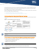
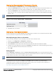
1. Navigate to Device Setup > Communication. 2. In the Default Credentials section, select the Edit link next to Dell. The page illustrated in Figure 3 appears. 3. Enter the SNMP Community String. Be sure to note the community string because it must match the SNMP trap community string, which is configured later in this document. Figure 3: Credentials in Device Setup > Communication 4.
Setting Up Recommended Timeout and Retries 1. In the Device Setup > Communication page, locate the SNMP Setting section. 2. Change the SNMP Timeout setting to a value or either 3, 4, or 5. This is the number of seconds that AirWave will wait for a response from a device after sending an SNMP request, so a smaller number is more ideal. 3. Change the SNMP Retries value to 10.
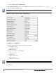
Table 1: AMP Setup> Network > Secondary Network Fields and Default Values Setting Default Description Primary ntp1.yourdomain.com Sets the IP address or DNS name for the primary NTP server. Secondary ntp2.yourdomain.com Sets the IP address or DNS name for the secondary NTP server. Enabling Support for Channel Utilization And Statistics To enable support for channel utilization statistics, you must have the following versions: l Dell Networking W-AirWave 7.
Controller Setup (Master And Local) Enabling these commands on AOS versions prior to 6.0.1.0 can result in performance issues on the controller. If you are running previous firmware versions such as AOS 6.0.0.0, you should upgrade to AOS 6.0.1 (to obtain RF utilization metrics) or 6.1 (to obtain RF utilization and classified interferer information) before you enter this command. The following commands are for AOS 6.4.
| Configuring W-AirWave for Global W-Series Infrastructure Dell Networking W-AirWave 8.
Chapter 3 Configuring a Dell Networking W Group in AirWave It is prudent to establish one or more Dell Networking W Groups within AirWave. During the discovery process you will move new discovered controllers into this group. This section contains the following topics: l "Basic Monitoring Configuration" on page 11 l "Advanced Configuration " on page 12 Basic Monitoring Configuration 1. Navigate to Groups > List. 2. Select Add. 3.
Figure 7: Group SNMP Version for Monitoring 7. Click Save and Apply when you are done. Advanced Configuration Refer to the Dell Networking W-AirWave 8.0 Controller Configuration Guide for detailed instructions. 12 | Configuring a Dell Networking W Group in AirWave Dell Networking W-AirWave 8.
Chapter 4 Discovering Dell Networking W-Series Infrastructure AirWave utilizes the Dell Networking W-Series topology to efficiently discover downstream infrastructure. This section guides you through the process of discovering and managing your Dell Networking W-Series device infrastructure.
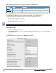
Figure 8: Dell Networking W Credentials in Device Setup > Add 4. Enter the required fields for configuration and basic monitoring: n Telnet/SSH Username n Telnet/SSH password n enable password 5. Enter the required fields for WMS Offload n SNMPv3 Auth Protocol n SNMPv3 Privacy Protocol n SNMPv3 Username n Auth Password n Privacy Password The protocols for SNMPv3 Auth and SNMPv3 Privacy should be SHA-1 and DES in order for WMS Offload to work.
6. Assign the controller to a Group and Folder. 7. Ensure that the Monitor Only option is selected. If you select Manage read/write, AirWave will push the group setting configuration, and existing device configurations will be deleted/overwritten. 8. Select Add. 9. Navigate to the APs/Devices > New page. 10. Select the Dell Networking W-Series master controller you just added from the list of new devices. 11. Ensure Monitor Only option is selected. 12. Select Add.
| Discovering Dell Networking W-Series Infrastructure Dell Networking W-AirWave 8.
Chapter 5 AirWave and Dell Networking W-Series Integration Strategies This section describes strategies for integrating AirWave and Dell Networking W-Series devices and contains the following topics: l "Integration Goals" on page 17 l "Example Use Cases" on page 18 l "Prerequisites for Integration" on page 19 l "Enable Statistics Utilizing AirWave" on page 19 l "WMS Offload with AirWave" on page 20 l "Define AirWave as a Trap Host Using the AOS CLI" on page 21 l "Understanding WMS Offload Impa
l WMS Offload encompasses enable stats or enable stats is a subset of WMS Offload. l Unless you enable stats on the local controllers in a master/local environment, the local controllers do not populate their MIBs with any information about clients or rogue devices discovered/associated with their APs. Instead the information is sent upstream to master controller.
l You are in the process of converting their older third-party WLAN devices to Dell Networking W-Series devices and want a unified IDS dashboard for all WLAN infrastructure. l You want to relate Auth failures to a client device, AP, Group of APs, and controller. AirWave provides this unique correlation capability. See "Define AirWave as a Trap Host Using the AOS CLI" on page 21. When to Use Channel Utilization l You have a minimum version of AOS 6.1.0.0.
Figure 10: Offload WMS Database field in Groups > Basic 6. Select Save and Apply. 7. Select Save. This will push a set of commands via SSH to all Dell Networking W-Series local controllers. AirWave must have read/write access to the controllers in order to push these commands. This process will not reboot your controllers. If you do not follow the above steps, local controllers will not be configured to populate statistics.
This process will not reboot your controllers. See "AOS and AirWave CLI Commands" on page 35 for information on how to utilize the AOS CLI to enable stats for WMS Offload. The SNMPv3 user's Auth Password and Privacy Password must be the same. Do not enter these commands; these are pushed by AirWave while enabling WMS Offload.
Ensure the source IP of the traps match the IP that AirWave uses to manage the controller, see Figure 11. Navigate to APs/Devices > Monitor to validate the IP address in the Device Info section. Figure 11: Verify IP Address on APs/Devices > Monitor Page Verify that there is a SNMPv2 community string that matches the SNMP Trap community string on the controller.
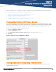
Understanding WMS Offload Impact on Dell Networking W-Series Infrastructure When offloading WMS, it is important to understand what functionality is migrated to AirWave and what functionality is deprecated. The following AOS tabs and sections are deprecated after offloading WMS: l Plan - The tab where floor plans are stored and heatmaps are generated. Before offloading WMS, ensure that you have exported floor plans from AOS and imported them into AirWave.
| AirWave and Dell Networking W-Series Integration Strategies Dell Networking W-AirWave 8.
Chapter 6 Dell Networking W-Series Specific Capabilities in AirWave This section discusses Dell Networking W-Series specific capabilities in AirWave and contains the following topics: l "Dell Networking W-Series Traps for RADIUS Auth and IDS Tracking" on page 25 l "Remote AP Monitoring" on page 26 l "ARM and Channel Utilization Information" on page 26 l "Viewing Controller License Information" on page 30 l "Rogue Device Classification" on page 31 l "Rules-Based Controller Classification" on page
Remote AP Monitoring To monitor remote APs, follow these steps: 1. From the APs/Devices > List page, filter on the Remote Device column to find remote devices. 2. To view detailed information about the remote device, select the device name. The page illustrated in Figure 15 appears. Figure 15: Remote AP Detail Page You can also see if there are users plugged into the wired interfaces in the Connected Clients list below the Clients and Usage graphs.
Figure 16: ARM and Channel Utilization Graphs See the Dell Networking W-AirWave 8.0 User Guide more information about the data that displays in the Radio Statistics page for these devices. VisualRF and Channel Utilization 1. Navigate to a floor plan by clicking on the thumbnail on a device’s APs/Devices > Monitor page or navigating to VisualRF > Floor Plans page. 2. Select the Overlays menu. Figure 17: Overlays 3. Select the Ch. Utilization overlay. 4. Select Current or Maximum (over last 24 hours).
Figure 18: Channel Utilization in VisualRF (Interference/2.4 GHz) Configuring Channel Utilization Triggers 1. Navigate to System > Triggers and select Add. 2. Select Channel Utilization from the Type drop-down menu as seen on Figure 19: 28 | Dell Networking W-Series Specific Capabilities in AirWave Dell Networking W-AirWave 8.
Figure 19: Channel Utilization Trigger 3. Enter the duration evaluation period. 4. Click the Add New Trigger Condition button. 5. Create a trigger condition for Radio Type and select the frequency to evaluate. 6. Select total, receive, transmit, or interference trigger condition. 7. Set up any restrictions or notifications. (Refer to the Dell Networking W-AirWave 8.0 User Guide for more details.) 8. When you are finished, click Add.
Figure 20: Channel Utilization alerts Channel Utilization Alerts on the System > Alerts Page 1. Navigate to the System > Alerts page. 2. Sort the Trigger Type column and find Channel Utilization alerts. Figure 21: Channel Utilization alerts on the System > Alerts page View Channel Utilization in RF Health Reports 1. Navigate to Reports > Generated. 2. Find and select an RF Health report. 3. Scroll down to view most and least utilized 2.4 and 5 channel usage information.
Figure 23: License Popup from APs/Devices > Monitor page a controller Rogue Device Classification Complete the steps in this section if you have completed the WMS Offload procedure. After offloading WMS, AirWave maintains the primary ARM, WIPS, and WIDS state classification for all devices discovered over-the-air. See Table 3 below for details.
Controller classification can also be updated from RAPIDS > List via the Modify Devices link. All rogue devices will be set to a default controller classification of unclassified when WMS is first offloaded except for devices classified as valid. Rogue devices classified in AOS as valid will also be classified within AirWave as valid for their controller classification as well.
Rules-Based Controller Classification This section contains the following topics: l "Using RAPIDS Defaults for Controller Classification" on page 33 l "Changing RAPIDS Based on Controller Classification" on page 33 Using RAPIDS Defaults for Controller Classification 1. Navigate to the RAPIDS > Rules page and select the pencil icon beside the rule that you want to change. 2. In the Classification drop-down list, select Use Controller Classification (see Figure 26 below). 3. Click Save.
Figure 27: Configure Rules for Classification 4. Click Add. A new Controller Classification field displays. 5. Select the desired controller classification to use as an evaluation in RAPIDS. 6. Click Save. 34 | Dell Networking W-Series Specific Capabilities in AirWave Dell Networking W-AirWave 8.
Appendix A AOS and AirWave CLI Commands Enable Channel Utilization Events Enabling these commands on AOS versions prior to 6.1 can result in performance issues on the controller. To enable channel utilization events utilizing the Dell Networking W-Series AOS CLI, use SSH to access a local or master controller’s command-line interface, enter enable mode, and issue the following commands: (Controller-Name) # configure terminal Enter Configuration commands, one per line.
(Controller-Name) (config) # mobility-manager user (Controller-Name) (config) # write mem This command creates an SNMPv3 user on the controller with the authentication protocol configured to SHA and privacy protocol DES. The user and password must be at least eight characters because the Net-SNMP package in AirWave adheres to this IETF recommendation. AOS automatically creates Auth and Privacy passwords from this single password.
To disable debugging, SSH into the controller, enter enable mode, and issue the following commands: (Controller-Name) # show running-config | include logging level debugging If there is output, then use the following commands to remove the debugging: (Controller-Name) # configure terminal Enter Configuration commands, one per line.
wlsxClientAssociatedToHostedNetwork wlsxClientAssociatingOnWrongChannel wlsxClientFloodAttack wlsxCTSRateAnomaly wlsxDisconnectStationAttackAP wlsxDisconnectStationAttackSta wlsxEAPRateAnomaly wlsxFataJackAttack wlsxFrameBandWidthRateExceeded wlsxFrameFragmentationRateExceeded wlsxFrameLowSpeedRateExceeded wlsxFrameNonUnicastRateExceeded wlsxFrameReceiveErrorRateExceeded wlsxFrameRetryRateExceeded wlsxHostOfWirelessNetworkContainment wlsxHotspotterAttackDetected wlsxHT40MHzIntoleranceAP wlsxHT40MHzIntoleran
wlsxSignAPAsleap wlsxSignAPDeauthBcast wlsxSignAPNetstumbler wlsxSignAPNullProbeResp wlsxSignatureMatchAP wlsxSignatureMatchSta wlsxSignStaAirjack wlsxSignStaAsleap wlsxSignStaDeauthBcast wlsxSignStaNetstumbler wlsxSignStaNullProbeResp wlsxStaAssociatedToUnsecureAP wlsxStaImpersonation wlsxStaPolicyViolation wlsxStaRepeatWEPIVViolation wlsxStaUnAssociatedFromUnsecureAP wlsxStaWeakWEPIVViolation wlsxTKIPReplayAttack wlsxUserEntryAttributesChanged wlsxValidClientMisassociation wlsxValidClientNotUsingEncryptio
| AOS and AirWave CLI Commands Dell Networking W-AirWave 8.
Appendix B AirWave Data Acquisition Methods The tables below describe the different methods through which AirWave acquires data from Dell Networking W-Series devices on the network. The tables use the following symbols: l ç Initiated by W-AirWave l è Initiated by Controller, or Instant Virtual Controller l é Initiated by W-AirWave to a separate device Table 5: Data Flow between Controllers and W-AirWave Data Type SNMP 802.
Table 5: Data Flow between Controllers and W-AirWave (Continued) Data Type SNMP Traps SSH AMON PAPI Syslog NMAP FTP/TFTP DNS Notes When AMON is used for client monitoring, W-AirWave uses this at startup time to get current user status. è Firewall Stats é Firmware Images ç Images are sent to controller over FTP/TFTP. They can be transferred to W-AirWave via HTTPS. è IDS Events ç Interface Monitoring Available in W-AirWave 8.0 and beyond.
Table 6: Data Flow between Instant Devices and W-AirWave Data Type SNMP Traps SSH AMON PAPI Syslog HTTPS ICMP NMAP FTP/TFTP DNS Notes All Monitoring Data è VC sends data to W-AirWave every minute in an HTTP POST. Configuration Commands è When W-AirWave needs to send data to a VC, it sends it in the HTTPS response.
Appendix C WMS Offload Details WMS Offload instructs the master controller to stop correlating ARM, WIPS, and WIDS state information among its local controllers because AirWave will assume this responsibility. Figure 28 depicts how AirWave communicates state information with local controllers. Figure 28: ARM/WIPS/WIDS Classification Message Workflow State Correlation Process 1. AP-1-3-1 hears rogue device A. 2.
Using AirWave as a Master Device State Manager AirWave offers the following benefits as a master device state manager: l Ability to correlate state among multiple master controllers. This will reduce delays in containing a rogue device or authorizing a valid device when devices roam across a large campus. l Ability to correlate state of third party access points with ARM. This will ensure that Dell Networking W-Series infrastructure inter-operates more efficiently in a mixed infrastructure environment.
Appendix D Increasing Location Accuracy This appendix describes the impact that band steering can have on location accuracy. It also explains how RTLS can be used to increase location accuracy. Understand Band Steering's Impact on Location Band steering can negatively impact location accuracy when testing in a highly mobile environment. The biggest hurdles to overcome are scanning times in 5 GHz frequency.
Figure 30: Typical Tag Deployment Prerequisites You will need the following information to monitor and manage your Dell Networking W-Series infrastructure. l Ensure that the AirWave server is already monitoring Dell Networking W-Series infrastructure. l Ensure that the WMS Offload process is complete. l Ensure that the firewall configuration for port 5050 (default port) supports bidirectional UDP communication between the AirWave server's IP address and each access point's IP address.
Figure 31: RTLS Fields in AMP Setup> General Enable RTLS on the Controller RTLS can only be enabled on the master controller and it will automatically be propagated to all local controllers. SSH into master controller, enter enable mode, and issue the following commands: (Controller-Name) # configure terminal Enter Configuration commands, one per line.
Troubleshooting RTLS You can use either the WebUI or CLI to ensure the RTLS service is running on your AirWave server. Using the WebUI to See Status 1. In the AirWave WebUI, navigate to the System > Status page. 2. Scroll down through the Services list to locate the RTLS service, as shown below.
data_rate => 2 noise_floor => 85 payload => rssi => -64 tag_mac => 00:14:7E:00:4C:E4 timestamp => 303139810 tx_power => 19 Verify external applications can see WiFi Tag information by running the Tag XML API: https:///visualrf/rfid.xml You should see the following XML output:
| Increasing Location Accuracy Dell Networking W-AirWave 8.
Appendix E Feature Implementation Schedule This appendix describes the feature implementation schedule for AirWave. Table 8: Feature Implementation Schedule for AirWave Feature AirWave Implementation HTML5-based UI for VisualRF 8.0 VisualRF Floor Upload Wizard 8.0 VisualRF Navigation Improvements 8.0 AppRF Overlay 8.0 AppRF Reports 8.0 UCC Visability 8.0 Additive Licensing 8.0 Client Health Graph 8.0 New Supported Devices 8.0 Dell Networking W-AirWave 8.