Dell W-AP92, W-AP93, W-AP104, W-AP105, and W-AP175 Wireless Access Points with Dell AOS FIPS Firmware Non-Proprietary Security Policy FIPS 140-2 January 26, 2015 This is to advise that the Aruba Networks document entitled “FIPS 140-2 Non-Proprietary Security Policy for Aruba AP-92, AP-93, AP-104, AP-105, and AP-175 Wireless Access Points” Version 2.1, dated August 2014, applies to Dell W-AP92, W-AP93, W-AP104, W-AP105, and W-AP175 Wireless Access Points with Dell AOS FIPS Firmware.
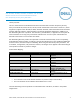
Dell Networking W-AP92 and W-AP93 Product Images (no rebranding of the exterior, except labeling): Aruba Networks AP-92 and AP-93 Product Images: Dell W-AP92/3, W-AP104/5 and W-AP175 Wireless Access Points FIPS 140-2 2
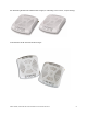
Dell Networking W-AP104 and W-AP105 Product Images (no rebranding of the exterior, except labeling): Aruba Networks AP-104 and AP-105 Product Images: Dell W-AP92/3, W-AP104/5 and W-AP175 Wireless Access Points FIPS 140-2 3
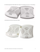
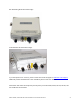
Dell Networking W-AP175 Product Image: Aruba Networks AP-175 Product Image: If you have questions or concerns, please contact Dell Technical Support at www.dell.com/support, additional product documentation is also available by device under user manuals.
FIPS 140-2 Non-Proprietary Security Policy for Aruba AP-92, AP-93, AP-104, AP-105, AP-175 Wireless Access Points Version 2.1 August 2014 Aruba Networks™ 1322 Crossman Ave.
Copyright © 2014 Aruba Networks, Inc. Aruba Networks trademarks include ,Aruba Networks®, Aruba Wireless Networks®, the registered Aruba the Mobile Edge Company logo, Aruba Mobility Management System®, Mobile Edge Architecture®, People Move. Networks Must Follow®, RFProtect®, Green Island®. All rights reserved. All other trademarks are the property of their respective owners.
1 INTRODUCTION .................................................................................................................................5 1.1 2 ACRONYMS AND ABBREVIATIONS ................................................................................................... 5 PRODUCT OVERVIEW ......................................................................................................................6 2.1 AP-92................................................................................
3.2.3.2 3.2.4 AP-104 TEL Placement ........................................................................................................ 20 3.2.4.1 To detect opening of the chassis cover: ............................................................................ 20 3.2.4.2 To detect access to restricted ports: .................................................................................. 20 3.2.5 AP-105 TEL Placement ...........................................................................
1 Introduction This document constitutes the non-proprietary Cryptographic Module Security Policy for the AP-92, AP93, AP-104, AP-105 and AP-175 Wireless Access Points with FIPS 140-2 Level 2 validation from Aruba Networks. This security policy describes how the AP meets the security requirements of FIPS 140-2 Level 2, and how to place and maintain the AP in a secure FIPS 140-2 mode. This policy was prepared as part of the FIPS 140-2 Level 2 validation of the product.
2 Product Overview This section introduces the various Aruba Wireless Access Points, providing a brief overview and summary of the physical features of each model covered by this FIPS 140-2 security policy. 2.1 AP-92 This section introduces the Aruba AP-92 Wireless Access Point (AP) with FIPS 140-2 Level 2 validation. It describes the purpose of the AP, its physical attributes, and its interfaces. The Aruba AP-92 is a high-performance 802.11n (2x2:2) MIMO, single-radio 2.4 GHz or 5 GHz (802.
2.1.1.3 12V DC power supply Indicator LEDs There are 5 bicolor (power, ENET and WLAN) LEDs which operate as follows: Table 1- AP-92 Indicator LEDs Label Function Action Status PWR AP power / ready status Off No power to AP Red Initial power-up condition Flashing – Green Device booting, not ready On – Green Device ready Off Ethernet link unavailable On – Amber 10/100Mbs negotiated On – Green 1000Mbs Ethernet link negotiated Flashing Ethernet link activity Off 2.
conjunction with Aruba Mobility Controllers to deliver high-speed, secure user-centric network services in education, enterprise, finance, government, healthcare, and retail applications. 2.2.1 Physical Description The Aruba AP-92 Access Point is a multi-chip standalone cryptographic module consisting of hardware and software, all contained in a hard plastic case. The module contains an 802.
Label Function ENET Ethernet Network Link Status / Activity 11b/g/n 2.4GHz Radio Status 11a/n 5GHz Radio Status Action Status Flashing – Green Device booting, not ready On – Green Device ready Off Ethernet link unavailable On – Amber 10/100Mbs negotiated On – Green 1000Mbs Ethernet link negotiated Flashing Ethernet link activity Off 2.4GHz radio disabled On – Amber 2.4GHz radio enabled in WLAN mode On – Green 2.4GHz radio enabled in 802.11n mode Flashing - Green 2.
FIPS Kit o 4010061-01 (Part number for Tamper Evident Labels) The exact firmware version validated was: 2.3.1.1 ArubaOS 6.3.1.7-FIPS Dimensions/Weight The AP has the following physical dimensions: 132 mm x 135 mm x 45 mm (5.2" x 5.3" x 1.8") 0.3 kg (10.56 oz) 2.3.1.2 Interfaces The module provides the following network interfaces: 1 x 10/100/1000 Base-T Ethernet (RJ45) Ports 802.
11a/n 5GHz Radio Status Flashing - Green 2.4GHz Air monitor or RFprotect sensor Off 5GHz radio disabled On - Amber 5GHz radio enabled in WLAN mode On – Green 5GHz radio enabled in 802.11n mode Flashing - Green 5GHz Air monitor or RFprotect sensor 2.4 AP-105 This section introduces the Aruba AP-105 Wireless Access Point (AP) with FIPS 140-2 Level 2 validation. It describes the purpose of the AP, its physical attributes, and its interfaces. The Aruba AP-105 is a high-performance 802.
1 x RJ-45 console interface (disabled in FIPS mode by TEL) The module provides the following power interfaces: 48V DC via Power-over-Ethernet (POE) 12V DC power supply 2.4.1.
flexibility in high-density campuses, storage yards, warehouses, container/transportation facilities, extreme industrial production areas and other harsh environments. 2.5.1 Physical Description The Aruba AP-175 Access Point is a multi-chip standalone cryptographic module consisting of hardware and software, all contained in a hard case. The module contains two 802.11 a/b/g/n transceivers, and 4 x Ntype female interfaces (2 x 2.
Label LED Position Function Action Status PWR D11 AP power / system status Off No power to AP Red System Alarm Flashing - Green Power did not connect well or equipment failure On - Green Device ready Off Ethernet link unavailable On - Yellow 10/100Mbs Ethernet link negotiated On - Green 1000Mbs Ethernet link negotiated Flashing Ethernet link activity Off Radio0 disabled On - Orange Radio0 enabled Off Radio1 disabled On - Blue Radio1 enabled On - Orange/Blue SS1 to SS4 LEDs t
3 Module Objectives This section describes the assurance levels for each of the areas described in the FIPS 140-2 Standard. . 3.
Allow 24 hours for the TEL adhesive seal to completely cure. Record the position and serial number of each applied TEL in a security log. Once applied, the TELs included with the AP cannot be surreptitiously broken, removed or reapplied without an obvious change in appearance: Each TEL has a unique serial number to prevent replacement with similar label. To protect the device from tampering, TELs should be applied by the Crypto Officer as pictured below: 3.2.
Figure 3 - Aruba AP-92 TEL placement right view Figure 4 - Aruba AP-92 TEL placement top view Figure 5 - Aruba AP-92 TEL placement bottom view 17
3.2.3 AP-93 TEL Placement This section displays all the TEL locations of the Aruba AP-93. The AP-93 requires a minimum of 3 TELs to be applied as follows: 3.2.3.1 To detect access to restricted ports: 1. 3.2.3.2 Spanning the serial port To detect opening of the chassis cover: 2. Spanning the bottom and top chassis covers on the left side 3.
Figure 7 - Aruba AP-93 TEL placement left view Figure 8 - Aruba AP-93 TEL placement right view Figure 9 - Aruba AP-93 TEL placement bottom view 19
Figure 10 - Aruba AP-93 TEL placement top view 3.2.4 AP-104 TEL Placement This section displays all the TEL locations of the Aruba AP-104. The AP-104 requires a minimum of 3 TELs to be applied as follows: 3.2.4.1 3.2.4.2 To detect opening of the chassis cover: 1. Spanning the bottom and top chassis covers on the left side 2. Spanning the bottom and top chassis covers on the right side To detect access to restricted ports: 3.
Figure 13 - Aruba AP-104 TEL placement right view Figure 14 - Aruba AP-104 TEL placement top view Figure 15 - Aruba AP-104 TEL placement bottom view 21
3.2.5 AP-105 TEL Placement This section displays all the TEL locations of the Aruba AP-105. The AP-105 requires a minimum of 3 TELs to be applied as follows: 3.2.5.1 3.2.5.2 To detect opening of the chassis cover: 1. Spanning the bottom and top chassis covers on the left side 2. Spanning the bottom and top chassis covers on the right side To detect access to restricted ports: 3.
Figure 18 - Aruba AP-105 TEL placement right view Power Input Inlet Figure 19 - Aruba AP-105 TEL placement top view Figure 20 - Aruba AP-105 TEL placement bottom view 23
3.2.6 AP-175 TEL Placement This section displays all the TEL locations of the Aruba AP-175. The AP-175 requires a minimum of 6 TELs to be applied as follows: 3.2.6.1 3.2.6.2 To detect access to restricted ports: 1. Spanning the USB console port 2. Spanning the power connector plug (AP-175P only) 3. Spanning the hex screw To detect opening of the chassis cover: 4. Spanning the top and bottom chassis covers on the left side 5.
Figure 23 - Aruba AP-175 TEL placement left view Figure 24 - Aruba AP-175 TEL placement right view Figure 25 - Aruba AP-175 TEL placement top view Figure 26 - Aruba AP-175 TEL placement bottom view 25
3.2.7 Inspection/Testing of Physical Security Mechanisms Table 7 - Inspection/Testing of Physical Security Mechanisms Physical Security Mechanism Recommended Test Frequency Guidance Tamper-evident labels (TELs) Once per month Examine for any sign of removal, replacement, tearing, etc. See images above for locations of TELs Opaque module enclosure Once per month Examine module enclosure for any evidence of new openings or other access to the module internals. 3.
Control Input Interface Status Output Interface Power Interface USB 2.0 port 10/100/1000 Ethernet Ports 802.11a/b/g/n/ac Antenna Interfaces Reset button 10/100/1000 Ethernet Ports 802.11a/b/g/n/ac Antenna Interfaces LEDs Power Supply Power-over-Ethernet (POE) Data input and output, control input, status output, and power interfaces are defined as follows: Data input and output are the packets that use the networking functionality of the module.
4 Roles, Authentication and Services 4.1 Roles The module supports the roles of Crypto Officer, User, and Wireless Client; no additional roles (e.g., Maintenance) are supported. Administrative operations carried out by the Aruba Mobility Controller map to the Crypto Officer role. The Crypto Officer has the ability to configure, manage, and monitor the module, including the configuration, loading, and zeroization of CSPs.
o Wireless Client role: in Mesh Remote Mesh Point FIPS AP configuration, a wireless client can create a connection to the module using WPA2 and access wireless network access services. 4.1.1 Crypto Officer Authentication In each of FIPS approved modes, the Aruba Mobility Controller implements the Crypto Officer role. Connections between the module and the mobility controller are protected using IPSec.
Authentication Mechanism Mechanism Strength RSA Certificate based authentication (CO role) The module supports 2048-bit RSA keys. RSA 2048 bit keys correspond to 112 bits of security. Assuming the low end of that range, the associated probability of a successful random attempt is 1 in 2^112, which is less than 1 in 1,000,000 required by FIPS 140-2. ECDSA-based authentication (IKEv2) ECDSA signing and verification is used to authenticate to the module during IKEv2.
Service Description CSPs Accessed (see section 6 below for complete description of CSPs) Creation/use of secure management session between module and CO The module supports use of IPSec for securing the management channel. 14, 21, 22, 23, 24 (read) Creation/use of secure mesh channel The module requires secure connections between mesh points using 802.
Use of WPA pre-shared key for establishment of IEEE 802.11i keys When the module is in advanced Remote AP configuration, the links between the module and the wireless client are secured with 802.11i. This is authenticated with a shared secret only. Wireless bridging services The module bridges traffic between the wireless client and the wired network. 25 (read) None 4.2.4 Unauthenticated Services The module provides the following unauthenticated services, which are available regardless of role.
5 Cryptographic Algorithms FIPS-approved cryptographic algorithms have been implemented in hardware and firmware. The firmware supports the following cryptographic implementations. ArubaOS OpenSSL Module implements the following FIPS-approved algorithms: o AES (Cert. #2680) o CVL (Cert. #152) o DRBG (Cert. #433) o ECDSA (Cert. #469) o HMAC (Cert. #1666) o KBKDF (Cert. #16) o RSA (Cert. #1379) o SHS (Cert. #2249) o Triple-DES (Cert. #1607) o RSA (Cert.
ALG[ANSIX9.31]: Key(gen)(MOD: 1024 PubKey Values: 65537) ALG[RSASSA-PKCS1_V1_5]: SIG(gen): 1024, SHS: SHA-1/SHA-256/SHA384/SHA-512, 2048, SHS: SHA-1 o ECDSA (Cert. #466; non-compliant with the functions from the CAVP Historical ECDSA List) FIPS186-2: SIG(gen): CURVES(P-256 P-384), SHS: SHA-1 ArubaOS UBOOT Bootloader implements the following FIPS-approved algorithms: o RSA (Cert. #1380) o SHS (Cert.
6 Critical Security Parameters The following Critical Security Parameters (CSPs) are used by the module: Table 12 - Critical Security Parameters # Name CSPs type Generation Storage and Zeroization Use 1 Key Encryption Key (KEK) Triple-DES 168-bit key Hardcoded during (three key Triple-DES manufacturing only). Stored in Flash. Zeroized by using command ‘ap wipe out flash’ Encrypts IKEv1/IKEv2 Preshared key, ECDSA private key and configuration parameters.
7 RNG seed key FIPS 186-2 RNG Seed key (512 bits) Derived using NONFIPS approved HW RNG Stored in plaintext in volatile memory. Zeroized on reboot. Seed 186-2 General purpose (x-change Notice); SHA-1 RNG 8 Diffie-Hellman private key Diffie-Hellman private key (224 bits) Generated internally during Diffie-Hellman Exchange Stored in the volatile memory. Zeroized after the session is closed.
14 IKEv1/IKEv2 Preshared key 8-64 character preshared key CO configured Stored encrypted in Flash with the KEK. Zeroized by changing (updating) the preshared key through the User interface. 15 skeyid HMAC-SHA1/256/384 (160/256/384 bits) Established during IKEv1 negotiation Stored in plaintext in Key agreement in volatile memory. IKEv1 Zeroized when session is closed.
21 RSA Private Key RSA 2048 bits private key Generated at time of manufacturing by the TPM. Stored in non-volatile memory (Trusted Platform Module). Zeroized by physical destruction of the module. 22 RSA public key RSA 2048 bits public key Generated at time of manufacturing by the TPM. Stored in non-volatile Used by memory. Zeroized by IKEv1/IKEv2 for physical destruction of device authentication the module.
30 802.11i Group Transient Key (GTK) 256-bit shared secret used to derive group (multicast) encryption and integrity keys 31 802.11i Group AESCCM Data Encryption/MIC Key 32 Factory CA Public Key Internally derived by AP which assumes “authenticator” role in handshake Stored in plaintext in volatile memory; zeroized on reboot Used to derive multicast cryptographic keys 128-bit AES-CCM key Derived from 802.
7 Self-Tests The module performs the following Self Tests after being configured into either Remote AP mode or Remote Mesh Portal mode. The module performs both power-up and conditional self-tests. In the event any self-test fails, the module enters an error state, logs the error, and reboots automatically.
o ArubaOS Crypto Module o o o CRNG Test to Approved RNG (FIPS 186-2 RNG) ECDSA Pairwise Consistency Test RSA Pairwise Consistency Test o ArubaOS Uboot BootLoader Module o Firmware Load Test - RSA PKCS#1 v1.5 (2048 bits) signature verification o CRNG tests to non-approved RNGs These self-tests are run for the Atheros hardware cryptographic implementation as well as for the Aruba OpenSSL and ArubaOS cryptographic module implementations. Self-test results are written to the serial console.
8 Secure Operation The module can be configured to be in the following FIPS approved modes of operations via corresponding Aruba Mobility Controllers that have been certificated to FIPS level 2: • Remote AP FIPS mode – When the module is configured as a Remote AP, it is intended to be deployed in a remote location (relative to the Mobility Controller). The module provides cryptographic processing in the form of IPSec for all traffic to and from the Mobility Controller.
6. If the staging controller does not provide PoE, either ensure the presence of a PoE injector for the LAN connection between the module and the controller, or ensure the presence of a DC power supply appropriate to the particular model of the module. 7. Connect the module via an Ethernet cable to the staging controller; note that this should be a direct connection, with no intervening network or devices; if PoE is being supplied by an injector, this represents the only exception.
represents the only exception. That is, nothing other than a PoE injector should be present between the module and the staging controller. 8. Once the module is connected to the controller by the Ethernet cable, navigate to the Configuration > Wireless > AP Installation page, where you should see an entry for the AP. Select that AP, click the “Provision” button, which will open the provisioning window. Now provision the CPSec Mode by filling in the form appropriately.
9. a. During the provisioning process as Remote Mesh Portal, if Pre-shared key is selected to be the Remote IP Authentication Method, the IKE pre-shared key (which is at least 8 characters in length) is input to the module during provisioning. Generation of this key is outside the scope of this policy. In the initial provisioning of an AP, this key will be entered in plaintext; subsequently, during provisioning, it will be entered encrypted over the secure IPSec session.
8. 9. Once the module is connected to the controller by the Ethernet cable, navigate to the Configuration > Wireless > AP Installation page, where you should see an entry for the AP. Select that AP, click the “Provision” button, which will open the provisioning window. Now provision the AP as Remote Mesh Portal by filling in the form appropriately. Detailed steps are listed in Section “Provisioning an Individual AP” of Chapter “The Basic User-Centric Networks” of the Aruba OS User Guide.