
Reference Guide

24
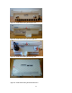
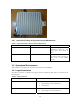
3.2.6 AP-175 TEL Placement
This section displays all the TEL locations of the Aruba AP-175. The AP-175 requires a minimum of 6
TELs to be applied as follows:
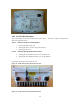
3.2.6.1 To detect access to restricted ports:
1. Spanning the USB console port
2. Spanning the power connector plug (AP-175P only)
3. Spanning the hex screw
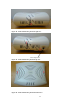
3.2.6.2 To detect opening of the chassis cover:
4. Spanning the top and bottom chassis covers on the left side
5. Spanning the top and bottom chassis covers on the right side
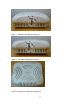
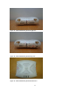
Following is the TEL placement for the AP-175:
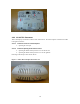
Figure 21 - Aruba AP-175 TEL placement front view
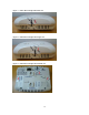
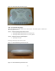
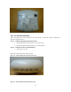
Figure 22 - Aruba AP-175 TEL placement back view