
Installation and Service Manual

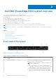
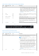
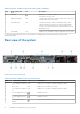
Table Of Contents
- Dell EMC PowerEdge R450 Installation and Service Manual
- Contents
- About this document
- Dell EMC PowerEdge R450 system overview
- Initial system setup and configuration
- Minimum to POST and system management configuration validation
- Installing and removing system components
- Safety instructions
- Before working inside your system
- After working inside your system
- Recommended tools
- Optional front bezel
- System cover
- Drive backplane cover
- Air shroud
- Cooling fans
- Intrusion switch module
- Drives
- Optional optical drive
- Drive backplane
- Cable routing
- System memory
- Processor and heat sink module
- Expansion cards and expansion card risers
- Optional serial COM port
- Optional BOSS S1 card
- Optional OCP card
- Front mounting front PERC module
- System battery
- Optional internal USB card
- VGA module
- Power supply unit
- Power interposer board
- System board
- Trusted Platform Module
- Control panel
- Jumpers and connectors
- System diagnostics and indicator codes
- Getting help
- Documentation resources

Dell EMC PowerEdge R450 system overview
The PowerEdge R450 system is a 1U server that supports:
● Up to two 3
rd
Generation Intel Xeon Scalable processors with up to 24 cores
● 16 DIMM slots
● Two redundant AC or DC power supply units
● 4 x 3.5-inch chip SATA (hard drive or SSD) drives.
● 4 x 3.5-inch hot-swappable SAS, SATA (hard drive or SSD) drives.
● 8 x 2.5-inch SAS, SATA (hard drive or SSD) drives.
For more information about supported drives, see the www.dell.com/poweredgemanuals section.
NOTE: All instances of SAS, SATA drives are seen as drives in this document, unless specified otherwise.
NOTE: For more information, see the Dell EMC PowerEdge R450 Technical Specifications on the product documentation
page.
Topics:
• Front view of the system
• Rear view of the system
• Inside the system
• Locating the Express Service Code and Service Tag
• System information label
• Rail sizing and rack compatibility matrix
Front view of the system
Figure 1. Front view of 4 x 3.5-inch drive system
Table 1. Features available on the front of the system
Item Ports, panels, and
slots
Icon Description
1 Left control panel N/A
Contains the system health, system ID, status LED, and the
iDRAC Quick Sync 2 (wireless) indicator.
NOTE: The iDRAC Quick Sync 2 indicator is available only
on certain configurations.
● Status LED: Enables you to identify any failed hardware
components. There are up to five status LEDs and an overall
system health LED (Chassis health and system ID) bar. For
more information, see the Status LED indicators section.
● Quick Sync 2 (wireless): Indicates a Quick Sync enabled
system. The Quick Sync feature is optional. This feature
2
8 Dell EMC PowerEdge R450 system overview