Dell Wyse ThinOS Version 8.
Notes, cautions, and warnings NOTE: A NOTE indicates important information that helps you make better use of your product. CAUTION: A CAUTION indicates either potential damage to hardware or loss of data and tells you how to avoid the problem. WARNING: A WARNING indicates a potential for property damage, personal injury, or death. © 2017 - 2018 Dell Inc. or its subsidiaries. All rights reserved. Dell, EMC, and other trademarks are trademarks of Dell Inc. or its subsidiaries.
Contents 1 Introduction..................................................................................................................... 7 About this guide..................................................................................................................................................................7 Technical support..........................................................................................................................................................
Configuring the authentication settings......................................................................................................................38 Configuring the central configurations............................................................................................................................. 56 Configuring the general central configurations ..........................................................................................................
Configuring the printer settings................................................................................................................................ 129 Reset features................................................................................................................................................................ 133 Resetting to factory defaults using G-Key reset........................................................................................................
Firmware upgrade using HTTP or HTTPS.......................................................................................................................183 Firmware upgrade using Wyse Management Suite version 1.1......................................................................................... 184 F Frequently asked questions.........................................................................................
1 Introduction Thin clients running Dell Wyse ThinOS firmware are designed solely for optimal thin client security and performance. These efficient purpose-built thin clients are virus and malware resistant and offer ultrafast access to applications, files and network resources within Citrix, Microsoft, VMware and Dell vWorkspace environments, and other leading infrastructures.
• ThinOS package updates—Updated ThinOS packages to a newer version. See, Dell Wyse ThinOS v8.5 Release Notes. • BIOS updates—Added new parameters for BIOS management. See, Dell Wyse ThinOS 8.5 Release Notes and Dell Wyse ThinOS 8.5 INI Reference Guide. • ThinOS UI-based updates: – Added a First Boot Wizard for a new or factory reset thin client. See, Configuring ThinOS using First Boot Wizard. – Added support for zero theme. See, Using zero theme. – Added a desktop wallpaper. Dell Wyse ThinOS v8.
2 Getting started Use the following information to quickly learn the basics and get started using your thin client: • Configuring ThinOS using the first boot wizard • Connecting to a remote server • Using your desktop • Configuring thin client settings and connection settings • Connecting to a printer • Connecting to a monitor • Locking the thin client • Signing off and shutting down • Additional getting started details NOTE: ThinOS is centrally managed and configured using INI files to aut
Figure 1.
Figure 2.
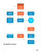
To configure the First Boot Wizard: 1. Connect a new thin client or existing thin client to the Ethernet using a wired connection. The existing thin client must be reset to factory default settings to enter the First Boot Wizard. 2. Turn on your thin client. The thin client checks for a wired network connection. If the network connection is successful, a welcome screen with the model name of your thin client is displayed. The thin client validates the IP address from DHCP.
• Locale—Select a language to start ThinOS in the regional specific language. • Keyboard Layout—Select a keyboard layout to set the keyboard layout in the regional specific language. Time Zone—Select a time zone to set the time zone for your thin client. • Time Server—Displays the IP addresses or host names with optional port number of time servers. • Advanced—Click Advanced to configure settings, such as daylight saving, time format, date format, and time servers.
• Connect the Ethernet cable to the thin client. • Click Define a wireless connection. From the list, select a wireless network, and click Connect. NOTE: – The option to define a wireless connection is not available on thin clients without a WLAN module. – To exit the Attach the Ethernet cable screen, and load the ThinOS system desktop, click Exit. After the connection is established, the thin client validates the IP address from DHCP.
• Citrix—The broker allows you to connect to full desktops using XenDesktop or individual applications using XenApp from a centralized host through Citrix Receiver Client. – Server Address—Enter the host name or IP address of the broker connection. – Enable theme: ThinOS Lite—Select this check box to boot the thin client in ThinOS Lite mode. – StoreFront style—Select this check box to enable the Citrix StoreFront based layout of published applications and desktops on the thin client.
Connecting to a remote server On your initial connection to central configuration, we recommended that you connect using a wired connection plug in the network-connected Ethernet cable to your thin client before starting the thin client to obtain the configurations desired by the administrator. This wired connection will also provide any wireless configurations provided by the administrator through INI files.
published applications and for backward compatibility with ThinOS 6.x versions. For more information on using the Classic Desktop, see Classic Desktop Features. • Users with a Zero Desktop—will see the Zero Desktop with the Zero Toolbar showing the assigned list of connections from which to select. This option is recommended for VDI and any full-screen only connections. For more information on using the Zero Desktop, see Zero Desktop Features.
Signing off and shutting down Use the Shutdown dialog box to select the available option you want: • Classic Desktop — Click Shutdown in the Connect Manager or Desktop Menu. • Zero Desktop — Click the Shutdown icon on the Zero Toolbar. NOTE: You can also configure automatic behavior after all desktop sessions are closed by using the Remote Connections dialog box, see Central configuration: Automating updates and configurations.
NOTE: • You can copy and paste between application sessions and between sessions and the desktop, however, this function depends on session server configurations. • In addition to the standard two-button mouse, the thin client supports a Microsoft Wheel Mouse used for scrolling. Other similar types of a wheel mouse may or may not work. To switch the left and right buttons, use the Peripherals dialog box, see Configuring the peripherals settings.
Option What It Does NOTE: The Close icon is grayed out for connections that are not open. Edit icon Opens the Connection Settings dialog box to change the connection options. NOTE: Depending on user privilege level, editing options may not be available for use. Add Connection Allows you to configure or add new connections.
• Clicking the User Name or clicking on the desktop, opens the desktop menu, see Using the desktop menu. NOTE: • User Name is the user who is logged-on and is located at the lower-left pane of the task bar.
c. System Tools—Provides information about devices, certificates, packages, global INI, user INI, wdm or ccm.ini. See System tools. d. Troubleshooting options—Displays Performance Monitor graphs that display client CPU, Memory and Networking information, Trace and Event log settings, CMOS management extract and restore settings, and other options that are useful for ThinOS troubleshooting. For more information, See Using the troubleshooting options and System tools. e.
g. Click Global Connection Settings tab to open and use the Global Connection Settings dialog box to configure settings that affect all the connections in the list. For more information on the Global Connection Settings dialog box, see Global connection settings. Login dialog box features While the Login dialog box allows you to log on to the server, it also allows you to: • Obtain system information. • Access Admin Mode to configure thin client settings.
• Event Log tab—Displays the thin client start-up steps normally beginning from system version to checking firmware or error messages that are helpful for debugging problems. The details about the monitors and USB connected to the thin client, and bluetooth initialization are also displayed.
3 Global Connection settings If you do not use INI files to provide central configuration (global connection settings) to users, you can use the Global Connection Settings dialog box to configure settings that affect all of the connections in your list of connections: • Zero desktop—Click Global Connection Settings in the list of connections. • Classic desktop—Click Global Connection Settings in the Connect Manager. To configure the Global Connection settings: 1.
a. Select the Enable H264 check box. This option allows H.264 decoding in Horizon Client. Enabling this option, improves the performance of high-end applications. To validate the H.264 decoding, navigate to the /tmp/vmware-user/ directory, open the vmware-mks-pid.log file, and check if the H264 support is enabled entry is registered in the log file. NOTE: • Blast H.264 feature is not supported on Wyse 5010 thin clients, Wyse 5040 thin clients, and Wyse 7010 thin clients. Blast H.
4 Configuring the connectivity This chapter helps you to understand various configuration settings for a secure connection. Connectivity menu includes: • Configuring the network settings. • Configuring the remote connections. • Configuring the central configurations. • Configuring the VPN manager. NOTE: To configure the settings on Classic desktop, click System Setup from the desktop menu, and use the configuration tabs.
The Network Setup dialog box is displayed. 2. Click the General tab, and use the following guidelines: a. To set the default gateway, select the type of network interface from the available options. 1. Single Network support—Either wireless or wired network is connected. • ENET — Click this option, if you want set up the Ethernet Wired Network Connection. • WLAN — Click this option, if you want set up the Wireless Network Connection.
Use of WINS is optional. Enter the network address of an available WINS name server. WINS allows you to specify remote systems by their host names rather than IP addresses. If a specific IP address (instead of a name) is entered for a connection, it is used to make the connection. These entries can be supplied through DHCP, if DHCP is used. DNS and WINS provide essentially the same function, name resolution.
b. Interpret DHCP Vendor-Specific Info — Select this check box for automatic interpretation of the vendor information. c. DHCP Vendor ID — Shows the DHCP Vendor ID when the dynamically allocated over DHCP/BOOTP option is selected. d. DHCP UserClass ID — Shows the DHCP UserClass ID when the dynamically allocated over DHCP/BOOTP option is selected. 3. Click OK to save the settings. Configuring the ENET settings To configure the ENET settings: 1.
provide information. Any value provided by the DHCP server replaces any value entered locally on the Options tab, however, locally entered values are used if the DHCP server fails to provide replacement values. • Statically specified IP Address —Select this option to manual enter the IP Address, Subnet Mask and Default Gateway: – IP Address — Must be a valid network address in the server environment. The network administrator must provide this information.
NOTE: The CA certificate must be installed on the thin client. Also note that the server certificate text field supports a maximum of approximately 255 characters, and supports multiple server names. – If you select the Connect to these servers check box, the box is enabled where you can enter the IP address of server. – Click Browse to find and select the Client Certificate file and Private Key file you want. NOTE: Make sure you select PFX file only.
a. Add—Use this option to add and configure a new SSID connection. You can configure the SSID connection from the available security type options.
After you configure the SSID connection, the added SSID connection is listed on the page of the WLAN tab. b. Remove—Use this option if you want to remove a SSID connection by selecting the SSID connection from the list. c. Properties—Use this option to view and configure the authentication properties of a SSID connection that is displayed in the list. d. Select the Disable Wireless Device check box, if you want to disable a wireless device. • 3.
a. Enter the HTTP proxy port number or HTTPS proxy port number, User name and Password in the respective fields. However, credential pass through ($UN/$PW) is not recommended because it starts before user sign on. Wyse Management Suite uses both HTTP/HTTPS and MQTT protocols to communicate with the WMS/MQTT server. However, the HTTP proxy cannot redirect TCP packages to the MQTT server which requires a SOCKS5 proxy server.
Configuring the remote connections Use the Remote Connections dialog box to configure thin client remote connections including ICA, RDP, Citrix XenDesktop, Microsoft, VMware View, Dell vWorkspace, and other broker server connections. This dialog box also enables you to configure visual options, and general connection settings.
NOTE: The Visual Experience tab is grayed out, if the StoreFront Style check box is selected for a Citrix Broker Server entered in the Broker Setup tab. a. Classic Desktop — Displays the full taskbar, desktop and Connect Manager familiar to ThinOS users. This option is recommended for terminal server environments and for backward compatibility with ThinOS 6.x versions. b. Zero Launchpad — Displays the new launch pad style GUI designed for VDI use.
Configuring the general options To configure the general options: 1. From the desktop menu, click System Setup, and then click Remote Connections. The Remote Connections dialog box is displayed. 2. Click the General Options tab, and use the following guidelines: a. Click the available options to select the action after you exit all open desktops. The available options are None, Sign-off automatically, Shut down the system automatically and Restart the system automatically.
The following authentication options are displayed: 3. • Imprivata— Configuring Imprivata OneSign server. • Caradigm—Configuring Caradigm server. • SECUREMATRIX— Configuring SECUREMATRIX. • HealthCast—Introduction to HealthCast. After configuring your preferred authentication, click OK to save the settings.
The following OneSign features or actions are supported: • Client and Broker Authentication – Citrix Xen App – Citrix Xen Desktop – VMware View • Kiosk Mode • Fast User Switching • Non-OneSign user VDI access • Hotkey Disconnect • Proximity card reader redirection • Guided Question and Answer login • Authenticate w/Password • Authenticate w/Password + Password Change • Authenticate w/Password + Password Change | New Password is Invalid • Authenticate w/Proximity Card + Password • Auth
– If you enable this feature by selecting the check box, the shutdown and restart icon is shown in ThinOS login and locked windows. – If you clear the check box, the shutdown and restart icon is grayed out. • FailedOneSignAuth Allow—Only yes or no options are supported. Non-OneSign user can log in to the Broker by clicking No radio button. • Logging Allow – OneSign logs could output on ThinOS with this feature. An INI configuration is needed correspondingly. – Loglevel=0/1/2/3. The default value is 0.
“F1 ~ F12”, "BKSP", “DEL”, “DOWN”, “END”, “ENTER”, “ESC”, “HOME”, “INS”, “LALT”, “LEFT”, “LCONTROL”, “NUMLOCK”, “PGDN”, “PGUP”, “RCONTROL”, “RIGHT”, RTALT”, “SPACE”, “TAB”, “UP”, “a~z”, “A~Z”, “0~9” and modifier “+”, “%”, “^” (Shift, Alt and Control) • 3. Suspend action—The server configuration controls this feature on ThinOS. Therefore a new INI is added— SuspendAction=0/1; 0 means lock, 1 means signoff.
8. Password Self-Services force enrollment feature Selecting this check box allows you to reset the primary authentication password. INI configuration for Imprivata OneSign Server A new INI parameter is added to the OneSignServer=AutoAccess=command. The new value is AutoAccess=Local. When AutoAccessis set to local, the ThinOS ignores the brokers that are set on the Imprivata OneSign Appliance and starts the broker/ connections which are defined in wnos.ini or local defined on the client.
1. Tap the proximity card. The card enrollment page is displayed. 2. Enter the credentials and then click OK. Proximity card is enrolled successfully.
Imprivata Bio-metric Single Sign-On Fingerprint identification feature is highly reliable, and cannot be easily replicated, altered, or misappropriated. The prerequisites of OneSign server are: • Imprivata v4.9 or later appliance version is needed that supports the WebAPI v5 and later versions. • Fingerprint identification license is required. Notes on Imprivata Bio-metric Single Sign-On • Supported protocols are RDP, ICA, and PCoIP.
• 2. Unlocking the Virtual Desktop using Fingerprint Authentication. • 46 Fingerprint authentication works on the ThinOS unlock window. Enable the Imprivata Virtual Channel from ThinOS Global Connection Settings.
• 3. When you lock the virtual desktop in the session, the Fingerprint window is displayed automatically. Managing Fingerprints on virtual desktop. • Legend Fingerprint Management is supported. • Fingerprint management with Imprivata Confirm ID enabled is not supported. This requires both supervisor and user to finish the enrollment and it is recommended to use Windows platform to perform this action. To manage fingerprints, do the following: a. Right-click the OneSign agent icon in System tray.
b. Click Manage Fingerprints, and enter the correct credentials in the displayed window to manage your Fingerprints. Configuring the Caradigm server Caradigm Single Sign-on and Context Management (SSO & CM) is the product of the Caradigm Company which provides Single Sign-on and Context Management Services. Caradigm solution has been integrated since ThinOS 8.1. To configure the Caradigm integration on ThinOS, do the following: 1.
a. SSO & CM Server—Enter the IP addresses of the Single Sign-On (SSO) and Context Management (CM) Servers. b. Default Group Name—Type the name of the default group in the Default Group Name box. c. Enable logoff remote desktop • 3. Select the check box to log off the current user from the session before system sign-off. • Clear the selection to disconnect from the session. Click OK to save the settings. Configuring the Caradigm Vault server To configure the Caradigm Vault server on ThinOS: 1.
4. Click SSO&CM → Advanced Configurations , and use the following guidelines: a. Ensure that the Enable Proximity Support check box is selected. b. Ensure that the Enable way2care check box is selected. 5. To prepare a certificate to the Caradigm Vault Server, use the following guidelines: The Caradigm Vault Server uses the certificate to validate the connection between the Tap Server and the thin client. a.
Use the Thin Client Certificates page to add certificates for the thin client devices. The certificate must be a text in PEM format, that is, a text-based Base64-encoded DER file. • • • Open the DER cert file on Notepad. Log in to the Vault Server Admin Console, and then click Appliance → Thin Client Certificates.
NOTE: HealthCast SSO Solution on ThinOS is a client-server solution. ThinOS provides the client-side functionality, but you must also install and configure the HealthCast Server components on a server system in order for the solution to work properly. Contact HealthCast on HealthCast website for one or more server installation executables, server requirements, and configuration information.
d. To import the client certificate, click Browse, and select the appropriate certificate you want to use. e. Click OK to save the settings. INI configuration To configure using INI parameters, add the following INI parameters to your wnos.ini file: HealthCastServer— The server address and options needed for the client to connect to the HealthCast Web API Server.
and you can follow the easy registration process. This is a one-time event after which you can use the card wherever HealthCast is installed. • 54 Manual login and lock/unlock terminal—If you do not have a card, or choose not to use your card, then you can manually log in using your user name and password. Administrators can disable manual login, if they wish, so that users can sign on with their proximity cards. You can also lock or unlock the terminal, if you have signed on with a manual login.
• Proximity card login and lock/unlock terminal—After the proximity card is registered, tap the card at a terminal to login. You can lock the session to secure it, but leave the remote session connected for fast access when you return. To do this, tap the proximity card and the session is locked. To resume the session, tap the card again. • Walk away—Terminals can be configured to lock or log off sessions that have been left open.
• Tap-Over—If a session is locked or left open, a second user can tap their own proximity card and this will disconnect the first session and log the second user into their own unique session. • Forgotten card—If you forget your card at home, you can receive a temporary card and register it for the day using the same easy registration process mentioned in this section.
File Servers/Path, Username and Password — Enter the IP address or host name of the file server that provides the system software and update images. The address can be supplied through DHCP, if DHCP is used. a. File Servers/Path — Allows maximum of 127 characters for file server, and maximum of 127 characters for root path. The data specifies part of the path to be used when the server is accessed. Multiple file servers/paths may be named, as long as all data fits in the length limitation. b.
By default, the WMS option is selected. Wyse Management Suite service automatically runs after the client boot up. If the first discovery, for example, the Wyse Management Suite service is not successful, then it seeks for the next priority, for example, WDM service. This continues until a discovery is successful. If all discoveries fail, then it is started again automatically after a fixed time—24 hours. a.
Example: _WMS_MQTT._TCP.WDADEV.com # Group Token DNS Record Type: DNS Text Record Name: _WMS_GROUPTOKEN. Value Returned: Group Token (as String) Example: _WMS_GROUPTOKEN .WDADEV.com # CA Validation DNS Record Type: DNS Text Record Name: _WMS_CAVALIDATION. Value Returned: TRUE or FALSE (as String) Example: _WMS_CAVALIDATION.WDADEV.com c. Group Registration Key—Enter the Group Registration Key as configured by your Wyse Management Suite administrator for the desired group.
1. Click WDM, and use the following guidelines: 2. WDM Servers—Enter the IP addresses or host names, if WDM is used. Locations can also be supplied through user profiles, if user INI profiles are used. 3. DNS Name Record—(Dynamic Discovery) Allows devices to use the DNS host name lookup method to discover a WDM Server. 4. DHCP Inform—(Dynamic Discovery) Allows devices to use DHCP Inform to discover a WDM Server. 5.
The VPN Manager dialog box is displayed. 3. Click New to create a new session. a. Session Name (up to 21 characters)—Enter the name of the Session Name. This is not a mandatory option. If the field is left blank, the VPN server name will be used as the session name. b. VPN server (up to 63 characters)—Enter the IP address of the VPN Server. This is defined as either an IP address or a host name. This is a mandatory option. c. Login Username (up to 31 characters)—Enter the Login Username.
When the connections are created, the description column lists the session name and the Auto column shows which connection is automatically connected when the unit restarts. Only one session can be set to auto-connect. 4. Click Connect. The connection status is displayed.
5 Configuring the connection brokers In a Virtual Desktop Infrastructure (VDI) environment, a connection broker is a software entity that allows you to connect to an available desktop. The connection broker facilitates the VDI environment to securely and efficiently manage the centrally hosted desktop environments. NOTE: • Linux hosted desktop in Citrix, VMware, and Dell vWorkspace brokers are supported. • Windows 10 desktop in multiple brokers is supported.
• 3. XenDesktop— Use this option, if you want to set default settings to XenDesktop. Click OK to save the settings. Citrix HDX RealTime Multimedia Engine or RealTime Optimization Pack HDX RealTime Optimization Pack (RTOP) provides a scalable solution to deliver audio-video conferencing and Voice over Internet Protocol (VoIP) enterprise telecommunication by using Microsoft Skype for Business. The Optimization Pack supports XenDesktop and XenApp environments to users on ThinOS devices.
Installing RTME package on ThinOS You are required to install the RTME.i386 package for the RTME feature to work on ThinOS. To install the RTME.i386 package: 1. Upload the RTME.i386.pkg to directory \wnos\pkg\. NOTE: For the latest RTME package version, see the latest Dell Wyse ThinOS Release Notes. 2. You must ensure that the INI autoload is not set to value 0. 3. Restart the thin client and wait till the auto-installation of packages is complete.
• Help and Hang up • Minimize/maximize or close the call video window • Perform Network Health check: – For RTME 1.8, press Ctrl+N to open the Network Health window. – For RTME 2.x, right-click the RTME icon on taskbar and select Call Statistics. The attributes, such as received packets, sent packets, video frame rate, video resolution, audio codec, and video codec are displayed in the above described window. Verifying the RTME 1.
Mode Optimized You can also view the Citrix HDX RealTime Connector for Microsoft Lync 2013 version and Citrix HDX RealTime Media Engine version in the dialog box. 3. Click the Audio Device tab to configure the RTME audio settings, such as speakers, microphone, and ringer settings. NOTE: The RTME audio device on ThinOS shows only one device from ThinOS local playback device. It can actually work the way they are configured at ThinOS local playback device and record device.
NOTE: USB redirection needs to be disabled for audio or video devices. 4. Connect to the remote desktop using SFB client. 5. Verify the RTME connector icon on taskbar. The status is displayed as Connected. 6. Verify the About and Settings option from the RTME connector menu. 7. Verify the audio/video devices from SFB client menus. 8. Establish the video/audio calls. 9. Pick up the calls by either clicking the mouse or using the headset button. 10.
The following message is displayed in the lower right pane during application refresh. 2. Applications are refreshed in Session bar list, Connect Manager list and App menu list. The following log is displayed in the Event Log window: ICA: refresh store “xxx”…” or “ICA: refresh PNAgent”xxx”… 3. For MultiFarm (StoreFront or PNAgent servers) or Multilogon (StoreFront or PNAgent servers), select a single server to refresh or click Refresh All to refresh all servers.
Limitations of Citrix icon refresh Following are the limitations of Citrix icon refresh: • Citrix icon refresh is supported in classic mode and storefront mode only. • Virtual Desktop Infrastructure (VDI) mode is not supported. Using multiple audio in Citrix session ThinOS supports multiple audio device utilizations in the XenDesktop or XenApp version 7.6 and later. You can connect or disconnect the audio devices anytime during the session, but the behavior is similar to a local desktop.
Prerequisites • NetScaler v12.0 and later is installed on your client. • SMS PASSCODE v9.0 SP1 is installed and configured in your network. You can download the SMS PASSCODE v9.0 file from download.smspasscode.com/public/6260/SmsPasscode-900sp1. • Remote Authentication Dial-In User Service (RADIUS) authentication policy is configured and bind to the NetScaler gateway server. • CensorNet app is installed and configured on your mobile device.
Configuring ICA connections To configure the ICA connections: 1. From the desktop menu, click System Setup, and then click Remote Connections. The Remote Connections dialog box is displayed. 2. In the Broker Setup tab, from the drop-down list, select the Broker type as None. 3. Click ICA connection protocol, and click Configure. The Default ICA dialog box is displayed. NOTE: Default ICA is always used for direct connection to a published application and not for StoreFront or PNAgent. 4.
Figure 3. Default ICA a. Server or Published Application—Select the type of connection to which the settings apply. b. Connection Description—Enter the descriptive name that is to appear in the connection list (38 characters maximum). c. Browser Servers—Enter a delimited (comma or semicolon) list of IP addresses or DNS-registered names of ICA servers that contains the master browsers list, or that could refer to another server that contains the list.
NOTE: The Host Name may be resolved using one of three mechanisms: ICA master browser, DNS or WINS. Master browser is the only mechanism that can resolve a published application unless manual entry is made in DNS for the application. DNS uses the default domain name in the network control panel to attempt to construct an FQDN but will also try to resolve the name without using the default. e.
Figure 4. Default ICA—Logon a. Logging on area—Enter Login User name, Password, Domain name, and Logon Mode. If the Login User name, Password, and Domain name boxes are not populated, you can enter the information manually in the ICA server login screen when the connection is made: • Login Username—Maximum of 31 characters is allowed. • Password—Maximum of 19 characters is allowed. • Domain Name — Maximum of 31 characters is allowed.
Figure 5. Default ICA—Options a. Autoconnect to local devices—Select any options (Printers, Serials, USB, Smart Cards, and Disks) to have the thin client automatically connect to the devices. b. Allow font smoothing—When selected, enables font smoothing (smooth type). c. Optimize for low speed link—When selected, allows optimization for low-speed connections, such as reducing audio quality and/or decreasing protocol-specific cache size. Intended for a connection spanning a WAN link or using dialup. d.
• The security question enrollment is not supported in Virtual Desktop Infrastructure (VDI) mode. Before resetting password or Unlocking account Before resetting your password or unlocking your account, you must register for the security questions enrollment. To register your answers for the security questions, do the following: 1. From the PNMenu, click the Manage Security Questions option (Classic and StoreFront only). The Security Questions Enrollment window is displayed. 2.
3. Click OK to register the security questions. Using Account Self-Service After the security questions enrollment is complete, when ThinOS is connected to a StoreFront server with Self-Service Password Reset enabled, the Account Self-Service icon is displayed in the sign-on window. NOTE: If you enter wrong password more than four times in the Sign-on window, the client automatically enters the unlock account process. 1. Click the Account Self-Service icon to unlock your account or reset your password.
2. Click Unlock account or Reset password based on your choice, and then click OK. Unlocking account After you register the security questions, do the following to unlock your account: 1. Choose a task (Unlock account) in Account Self-Service window. 2. Enter the user name. The Unlock Account dialog box is displayed. 3. Enter the registered answers to the security questions.
If the provided answers match the registered answers, then the Unlock Account dialog box is displayed. 4. 80 Click OK to successfully unlock your account.
NOTE: • If the provided answers are incorrect, the following error message is displayed. • If you provide the wrong answers more than three times, you cannot unlock the account or reset the password, and the following error messages are displayed. Resetting password After you register the security questions, do the following to reset your password: 1. Choose a task (Reset password) in Account Self-Service window. 2. Enter the user name. The Reset Password dialog box is displayed.
3. Enter the registered answers to the security questions. If the provided answers match the registered answers, then the Reset Password dialog box is displayed.
4. Enter and confirm the new password. 5. Click OK to successfully change the password. If you provide the wrong answers, you cannot reset the password, and an error message is displayed. QUMU or ICA Multimedia URL Redirection QUMU utilizes ICA Multimedia URL Redirection. You are required to install a browser plug-in for this feature to work. In earlier ThinOS releases, ICA Multimedia URL Redirection was partially supported. In ThinOS 8.
Verifying HTML5 Video Redirection—While the video is playing, a noticeable lag or jump in the video window is observed when you move the browser on the screen or scroll the browser. This behavior indicates that the video is being redirected. ThinOS event log for RAVE MMR is also displayed. Sometimes, the initial playback does not work. After several seconds, the video is refreshed automatically, and you need to click playback from start again. During this time, the video will redirect.
b.
Click HDX Monitor → Graphics → Thinwire Advanced → Encoder → CompatibilityEncoder; CompatibilityEncoder. From XenDesktop/ XenApp 7.11, the Encoder is changed to Deprecated. • For Wyse 3010 with ThinOS (T10) and Wyse 3020 with ThinOS (T10D): – ICA SuperCodec is always enabled without any limitation. – ThinOS event log displays ICA: SuperCodec enabled. NOTE: For ICA connections, there is no INI parameter.
Anonymous logon Anonymous logon feature enables the users to log into the StoreFront server configured with unauthenticated store without Active Directory (AD) user credentials. It allows unauthenticated users to access the applications instead of AD accounts. NOTE: Anonymous logon is not supported with legacy mode of StoreFront server.
Citrix UPD configuration on server a. 88 To enable the printer policy, use the following guidelines: 1. To enable the printer policy in XenApp 6.5– Go to the DDC Server, click Start → Citrix AppCenter . 2. Click Citrix Resources → XenApp → Policies → User → Settings → Printing → Client Printers and enable the Auto-create generic universal printer. 3. Click Printing → Drivers and set the Universal print driver usage to Use universal printing only from the dropdown menu available.
4. To enable the printer policy in XenApp/XenDesktop 7.5 and later versions, do the following: a. Go to the Citrix DDC Server, 1. Click Citrix studio → policies and add a policy. Enable the Auto-create generic universal printer option. 2. Set the Universal print driver usage to Use universal printing only from the drop-down menu.
b. Check registry and make sure the same driver has been installed. 1. Check the drivers in registry of the server or desktop which you want to connect. The server or desktop must have ps, pcl5, pcl4 drivers in the registry and the same driver must be installed on the server or desktop. 2. Go to HKEY_LOCAL_MACHINE\SOFTWARE\Citrix\UniversalPrintDrivers\. ThinOS does not support EMF and XPS. NOTE: The supported drivers in the following table are one of the supported drivers for Citrix UPD used in ThinOS.
2. Under HKEY_LOCAL_MACHINE\SOFTWARE\Citrix\UniversalPrintDrivers\PCL5c\, change DriverAlias and DriverName HP LaserJet 2200 Series PCL 5. Introduction to Flash Redirection The Flash Redirection solution is to off-load flash content to the ThinOS client, and locally render and decode the flash playback. The off-loading is conducted by Citrix HDX Flash Redirection. The local rendering and decoding process are conducted by customized flash player and other multimedia process that runs locally on ThinOS.
Supported Environment— Supports only Citrix Connections with XenApp 6.5 and later versions and XenDesktop 7.0 and later versions.
1. FR: Media type video/x-264 2. FR: Media type audio/mpeg For information about basic operations on Citrix HDX flash redirection and policies configurations, see Citrix documentation. Known Issues a. Playback flash videos in Internet Explorer browser with normal security settings. b. Playback with videos ≤ 720p; the 1080p video may show graphic issue. c.
This section provides information about how to configure a VMware broker connection on your ThinOS device, and other VMware features that you can configure on ThinOS. Configuring the VMware broker connection To configure the VMware broker setup: 1. From the desktop menu, click System Setup, and then click Remote Connections. The Remote Connections dialog box is displayed. 2.
In earlier version of ThinOS, when the broker times out, the user session is disconnected and the user is logged out from the broker. From ThinOS 8.2 release, ThinOS disconnects the user session from the broker, but does not force user logout. This is because the user has local connections other than the broker desktop, and these connections are active when the broker timeout is reached.
2. Log in to your View Admin web portal. 3. Navigate to Users and Groups → Unauthenticated Access, and add the two new anonymous users to the View Connection Manager. 4. Navigate to View Configurations → Select Servers → Connection Servers, and select your connection server. 5. Click Edit → Authentication tab, and select the Enabled for unauthenticated access check box. Do not select any users for the default unauthenticated user. 6.
4. Log in to the VMware Horizon broker. The domain list is hidden, and the server URL is displayed. Supporting VMware Real Time Audio-Video Use the Real-Time Audio-Video feature to run Skype and other online conference applications on the remote desktop. Using this feature, both audio and video devices that are connected to your thin client are available to use for VoIP in remote desktop. To know more about the VMware Real Time Audio-Video support, go to pubs.vmware.com/horizon-62-view/topic/ com.vmware.
4. Verify the audio settings in VoIP application. 5. Verify the video settings in VoIP application using the VMware virtual webcam.
6. Start the audio or video calls. Dependencies and known issues • Dependency: RTME.i386.pkg needs to be installed for RTAV video. • The answer call button of the local audio device, supported by HDX RTME, is not supported by RTAV. • RTAV does not support RDS desktop, for example, 2008 R2/ 2012 R2 according to VMware. • Support for PCoIP and Blast protocol only. RDP protocol is not supported according to VMware. • Webcam preferences are not supported.
Blast features Support on ThinOS Comments/ Known issues RDSH desktops Yes N/A RDSH applications Yes Application window does not support Seamless mode. For example, all applications open in single window because of the VMware limitation. RDSH application supports the PCoIP protocol from ThinOS 8.4, with same limitation.
For information about Blast Virtual Printing on ThinOS, see Blast Virtual Printing. Blast Virtual Printing Virtual printing with VMware Blast allows you to use local or network printers from the Blast desktop without the need of installing the additional print drivers on the remote desktop. For each printer configured locally on ThinOS, you must map the printer to the VMware Blast desktop. ThinOS Blast printer mapping is equivalent to VMware Blast virtual printing.
Figure 7. Options 7. Connect to a VMware Blast session. Go to Control Panel → Devices and Printers. The printer that is configured locally in ThinOS is mapped to the session. The mapped printer’s driver is TP PS Driver and the port is TPVM port. The virtual printer allows the ThinOS local printer to be mapped to the VMware Blast session without installing the printer driver in the session.
Configuring the Microsoft Remote Desktop broker connection To configure the Microsoft Remote Desktop broker setup: 1. From the desktop menu, click System Setup, and then click Remote Connections. The Remote Connections dialog box is displayed. 2. 3. In the Broker Setup tab, from the drop-down list, select Microsoft, and do the following: • Broker Server—Enter the IP address/Hostname/FQDN of the Broker Server.
a. Connection Description—Enter the descriptive name that is to appear in the connection list (38 characters maximum). b. Host Names—Use the list to select the valid DNS server name or the IP address of the server to which the thin client connection is to be made you can also use Browse next to the box to make the selection you want. For example, a list of WTS servers on the local network from which you can select. NOTE: The server name may be resolved using one of two mechanisms: DNS, and WINS.
You can reset the options on the Connection tab of the Connection Settings (RDP) dialog box. To do so, click the Reset VM command button. This command button is located in the upper-right of the dialog box. It appears only with a VDM broker connection. 5. Click Logon tab, and use the following guidelines: a. Logging on area —Enter login username, password, and domain name. If these boxes are not populated, you can enter the information manually in the RDP server login screen when the connection is made.
NOTE: The user name, password, and domain name fields are optional. If you leave any of these fields blank, interactive login is required and users must enter the information at login time. 6. Click Options tab, and use the following guidelines: a. b. c. d. Wallpaper—When selected, disables the desktop wallpaper. Menu / Window animation—When selected, disables the menu or window animation. Theme—When selected, disables the desktop themes.
RDP dynamic resizing The windows in an RDP session can be resized directly by using the mouse. How to work: 1. Launch an RDP session (Windows 8 or higher) by using Window mode and non-default resolution. 2. Use the mouse to change the size of the session window. Resizing the session window causes the MS media player’s frame region to dispatch. This is a server side issue. Features of RDP 8.1 Remote Desktop Protocol (RDP) H.264 and VOR is enabled by default for all ThinOS v8.5-based devices.
• When the feature is disabled, the following screen is displayed in the Event Log tab for disablement: • Also, when client resource used exceeds VOR limitation, there is no event log for VOR disablement. Work flow of dual display In dual display, the RDP feature only works within a limited resolution. The ‘maximum resolution possibly for the session’ for H.264 enablement is as follows: • RDP without force span which is the same as single display.
Platform Support GFX Support VOR Support RDP H. 264 Default GFX Default VOR Default H.264 HW/ SW decoder H.
2. Connection with TS gateway configured in unsupported OS (e.g. Windows Server 2008 R2), it uses TS gateway II and the logs are displayed as shown in the following screenshot: 3. When remote connection with TS gateway III closed: There are no additional logs displayed in the Event Log tab. Supporting RDP H.264 AVC444 RDP uses the ITU-T H.264 graphics compression (codec), also known as MPEG-4 AVC (Advanced Video Coding). In RDP 10, AVC/H.264 supports the full-screen AVC 444 mode.
Transmission Control Protocol (TCP). The data is transferred immediately over a full-duplex single socket connection, allowing messages to be sent and received from both endpoints in real time. As a pre-requisite, you must enable the WebSocket protocol on Windows Server 2016. ThinOS behavior • In the previous TS Gateway connection, the setup uses a two half-duplex communications between Terminal Server (TS) Gateway server and thin client. • In the ThinOS version 8.
This section provides information about how to configure the Amazon WorkSpaces (AWS) connection on your ThinOS device, and other Amazon WorkSpace features that you can configure on ThinOS. Configuring the Amazon WorkSpaces broker connection Amazon WorkSpaces connection is applicable only for PCoIP clients. To configure the Amazon WorkSpaces (AWS) broker setup: 1. From the desktop menu, click System Setup, and then click Remote Connections. The Remote Connections dialog box is displayed. 2.
6 Configuring thin client settings You can configure available thin client settings on the thin client using the following. Depending on user privilege level, some dialog boxes and options may not be available for use.
a. Screen Saver — Allows you to select the type of screen saver you want. The default is to Turn Off Screen. Other available screen savers are Flying Bubbles, Moving Image, Showing Pictures, and Playing Video. b. Timer — Select a time after which the screen saver is to be activated; either disable, 1 minute, 3 minutes, 5 minutes, 10 minutes (default), 15 minutes, or 30 minutes. When the thin client is left idle for the specified idle time, the screen saver is initiated. c.
3. Click OK to save the settings. Setting the time and date To configure the time and date settings: 1. From the desktop menu, click the System Setup, and then click System Preferences. The System Preference dialog box is displayed. 2. Click the Time/Date tab, and use the following guidelines: a. Time Zone— Select a time zone where the thin client operates from the drop-down list. Default value is Unspecified. b. Enable Daylight Saving— Allows you to enable the daylight saving settings.
Setting the custom information Use the Custom Info tab to enter configuration strings for use by WDM software. The configuration strings can contain information about the location, user, administrator, and so on. To set the custom information: 1. From the desktop menu, click System Setup, and then click System preferences. The System preference dialog box is displayed. 2. Click the Custom Info tab to enter configuration strings used by WDM software.
a. Select best display setting on DDC monitor—If the monitor is VESA DDC2B (Display Data Channel) compatible, selection of this option allows the thin client to automatically select the best resolution and refresh rate. If your monitor is not DDC compatible, then Monitor does not support Plug and Play message is displayed. Click OK to acknowledge the message and remove it from the screen. b.
1440 x 900 1600 x 900 1600 x 1200 1680 x 1050 1920 x 1080 1920 x 1200 1920 x 1440 2560 x 1080 2560 x 1440 2560 x 1600 3840 x 2160 d. Rotation —Select a rotation option; either None, Left turn 90 degrees, or Right turn 90 degrees. e. Desktop Color— Only 32 bit is permitted from ThinOS 8.2. This value is selected by default. f. Usage Help — This section contains brief instructions for using the Display dialog box and running the test. No operator entry can be made in this box.
Monitor resolutions Wyse 5060 thin client Wyse 3040 thin client 2560 x 1080 Supported Supported 2560 x 1440 Supported Supported 2560 x 1600 Supported Supported 3440 x 1440 Supported Not Supported 3840 x 2160–Dual 4K Supported Dual 3840 x 2160 is supported with Dual Display ports for 30 Hz display refresh rate. Not Supported For information about the tested monitors, see the latest Dell Wyse ThinOS Release Notes.
b. Main Screen—Select which of the two monitors you want to be the main screen (Screen1 or Screen2). The other screen is extended from the main screen. The other screen is extended from the main screen. When using a DVI to DVI/VGA splitter with VGA and DVI monitors at the same time, the VGA monitor will be the primary monitor. c. Layout—Select how you want the two monitors to be oriented to each other. Horizontal — where you move between the monitors from the left and right of the screens.
select the swap dual screens check box, you are able to set Main Screen to Screen2, but still have it at the left side or the top side, which is considered more user friendly. Changing Display Settings Dynamically From ThinOS 8.4 release, after you change the display settings, the changes will take effect immediately without a system restart. Single mode user scenario Go to System Setup → Display → General, and do the following: 1. Change resolution from DDC table or User defined display settings. 2.
The Peripherals dialog box is displayed. 2. Click the Keyboard tab and set the Character Set, Keyboard Layout, Delay Before Repeat and Repeat Rate parameters. The following table explains the keyboard parameters. Table 9. Keyboard settings Parameter 3. Description Character Set Specifies the character set. Each character is represented by a number. The ASCII character set, for example, uses the numbers 0 through 127 to represent all English characters and special control characters.
3. Select the Swap left and right mouse buttons check box to swap mouse buttons for left-handed operations. 4. Click OK to save the settings. Configuring the audio settings To configure the audio settings: 1. From the desktop menu, click System Setup, and then click Peripherals. 2. Click the Audio tab to select the volume settings for connected devices. The Peripherals dialog box is displayed. a. Click the Playback Devices tab to select the type of the audio from the drop-down menu.
• Select the check box to mute. b. Click the Recorded Devices tab to select the type of the record from the drop-down menu. • Use slider to control the volume settings for the record devices. • Select the check box to mute. c. Click Play to play the audio. d. The Recorder tab allows you to do the following tasks: • Collect information about the speaker and microphone currently being used. • Examine the performance of the speaker and microphone currently being used.
a. b. c. d. e. f. Select Port—Click the button to select the Port. Default is COM 1. Baud Rate—Select the Baud Rate from the drop-down list. Default is 9600. Parity—Click the button to select the Parity. Stop—Click the button to select the stop bits 1, 1.5, 2. Default value is 1. Size—Click the button to select the Character size 5, 6, 7, or 8 bits. Default is 8. Flow Control—Click the button to select Flow Control: Either None, XON/XOFF, CTS/RTS, or Both can be selected. Default is None. g.
NOTE: You can optimize performance and modify the frame rate per second, if the Optimize for CPU check box is not selected— supported values include 1/1, 1/2, 1/3, 1/4, 1/5, and 1/6– directly from the thin client (if the webcam supports Universal Video Driver). Also, this feature is CPU intensive and is recommended for high performance products. Configuring the touch screen settings Use the Touch Screen tab to configure touch screens that are connected to the thin client.
The Peripherals dialog box is displayed. 2. Click the Bluetooth tab, and use the following guidelines: Bluetooth enabled devices, such as headsets and mouses that are available in the Thin Client environment are listed in the Bluetooth page. The following attributes are displayed in the list. • Name—Specifies the name of the Bluetooth enabled device. • Type—Specifies the type of the Bluetooth enabled devices, such as headsets, mouses, and keyboards.
No • The Bluetooth device is not paired with the ThinOS device. Address—Displays the address of the Bluetooth device connected to your thin client. The following are the user scenarios and corresponding Bluetooth statuses displayed on the Bluetooth page. Table 11. User scenario User Scenario Status Device turned off Disconnected | Paired Device turned on Connected | Paired Device disconnected from ThinOS Disconnected | Not Paired • Scan— All Bluetooth devices enter into Page Scan mode.
USB hard disk—Do not plug in the USB hard disk with 10 or more drives, or do not plug in more than 10 USB keys into ThinOS client. ThinOS does not detect the USB disk with 10 or more drives. Known issue—Camera preview has some known issue. Configuring the printer settings Use the Printer Setup dialog box to configure network printers and local printers that are connected to the thin client. Through its USB ports, a thin client can support multiple printers.
b. Printer Name — (Required) Enter name you want displayed in your list of printers. most USB direct-connected printers report/fill in their printer name automatically. NOTE: If Enable LPD service for the printer is selected, the printer name becomes the queue name for other clients using LPR to print to this printer. c.
NOTE: Be sure to check with your vendor that the printer can accept Line Printer Request print requests. a. Select LPD —Select the port you want from the list. b. Printer Name —(Required) Enter name you want displayed in your list of printers. c. Printer Identification—Enter the type or model of the printer in the exact text of the Windows printer driver name— including capitalizations and spaces.
Configuring the SMBs settings To configure the SMBs settings: 1. From the desktop menu, click System Setup, and then click Printer. The Printer Setup dialog box is displayed. 2. Click SMBs tab, and use the following guidelines when printing to a Windows network printer. a. Select SMB—Select the SMB you want from the list. b. Printer Name—(Required) Enter the name to be displayed in your list of printers. c.
Using the printer setup options To configure the printer setup options: 1. From the desktop menu, click System Setup, and then click Printer. 2. Click the Options tab, and use the following guidelines: The Printer Setup dialog box is displayed. a. Default Printer —Select the printer you want to be the default printer from your list of available printers. b. Enable .print Client and Port —If you want to enable .print Client, select Enable .print Client , and then enter the port. 3.
Resetting to factory defaults using shutdown reset A high-privileged or stand-alone user can reset the thin client to factory default settings from the Shutdown dialog box. To reset the thin client to factory defaults: 1. From the desktop menu, click Shutdown. The Shutdown dialog box is displayed. 2. After starting your thin client you will see a Dell logo for a short period of time. 3. Click Restart the system to restart your thin client. 4.
7 Introduction to TCX Flash Redirection The Dell Wyse TCX Suite is a single software solution that provides full benefits of cloud client-computing without the limitations of competing software suites. The TCX Flash Redirection is one of the components of TCX Suite that enables the cloud client users to experience improved Flash video content performance in a remote computing environment. TCX Flash Redirection uses the client CPU to decode and render flash.
TCX FR on ThinOS is not working for certain flash video pages. However, the result is the same between FR over RDP, and FR over PCoIP. Dell recommends you to validate, and block the URL that does not work, before deploying TCX FR on all the systems.
8 Performing diagnostics Diagnostics include: • System tools • Using the troubleshooting options System tools Use the System Tools dialog box to view device details, package details and Global INI/User INI information. You can also import certificates using the Certificates tab. 1. From the desktop menu, click System Tools. The System Tools dialog box is displayed. 2. Click the Devices tab to display all the locally attached devices, including USB, Serial, and Parallel on applicable platforms.
NOTE: The Mirror File Server tab has been removed from the System Tools dialog box, as it can now be viewed in the Devices tab. 3. Click the Certificates tab, and use the following guidelines: a. Import the certificates by selecting either USB Storage or File Server from the drop-down list, and then click Import to import the required certificate. b. Click Delete to delete the imported certificate. c.
a. Click the Delete button to delete the selected package. b. Click the Delete all button to delete all the packages. The following packages are displayed in the Package tab: • base.i386.pkg • FR.i386.pkg—This package is introduced to support Flash Redirection. • RTME.i386.pkg—This package is introduced to support Citrix RTME. • Horizon.i386.pkg—This package is introduced to support VMware Blast protocol. The package version number is updated to match the latest Horizon client.
NOTE: In every ThinOS release, the packages may be updated to the latest version. For information about the latest package version, see the latest Dell Wyse ThinOS release notes. For information about updating the packages, see Firmware upgrade. 5. Click the Global INI tab to view wnos.ini information. 6. Click the User INI tab to view wnos.ini information. 7. Click the WDM INI to view the received WCM configurations.
WCM function is supported from WDM for comprehensive client configuration. Without configuration from server, the client loads the cached settings (wdm.ini), if available. Limitation To upgrade or downgrade firmware/image through WCM, you are required to enable WDM file server function by selecting the WTOS INI path upon checkin (FTP/HTTPS/HTTP/CIFS) check box in the WTOS preferences in the WDM configuration manager. User Scenario a. Create or edit client configurations from WCM (JSON).
b. 142 Select the target devices, and publish configuration settings through the Package Distribution Wizard.
For more information about WDM Package Manager and Profile Manager, refer to the WDM Admin Guide.
8. Click OK to save the settings. Simplified Certificate Enrollment Protocol Simplified Certificate Enrollment Protocol (SCEP) was designed to be used in a closed network where all end-points are trusted. The goal of SCEP is to support the secure issuance of certificates to network devices in a scalable manner. Within an enterprise domain, it enables network devices that do not run with domain credentials to enroll for certificates from a Certification Authority (CA).
2. Enter the appropriate values in the Request Certificate dialog box, and then click the Request Certificate button. The certificate request is sent to the server, and the client receives the response from server and installs both CA certificate and client certificate. 3. Click Ok to save the changes. NOTE: • If the SCEP server is on Windows Server, the CA certificate HASH provided by MS Windows server is always an MD5 hash type. • Request server URL must be an HTTP link.
Table 12. BTCTRoot.crt Certificate details Certificate field Default value/format Version V3 Serial number 02 00 00 b9 Signature algorithm sha1RSA Issuer Baltimore CyberTrust Root CN=Baltimore CyberTrust Root OU=CyberTrust O=Baltimore C=IE Valid from 2000–05–12 18:46:00 Valid to 2025–05–12 23:59:00 Subject Baltimore CyberTrust Root CN=Baltimore CyberTrust Root OU=CyberTrust O=Baltimore C=IE Public key RSA (2048 bits). Key bits are displayed in the lower pane of the window.
Certificate field Default value/format C=US Valid from 1998–05–18 00:00:00 Valid to 2028–08–12 23:59:59 Subject VeriSign Trust Network OU=VeriSign Trust Network OU=(c) 1998 VeriSign, Inc. – For authorized use only OU=Class 3 Public Primary Certification Authority – G2 O=VeriSign, Inc C=US Public key RSA (1024 bits). Key bits are displayed in the lower pane of the window.
Certificate field Default value/format Public key RSA (1024 bits). Key bits are displayed in the lower pane of the window. Thumbprint algorithm sha1 Thumbprint 0b 77 be bb cb 7a a2 47 05 de cc 0f bd 6a 02 fc 7a bd 9b 52 Certificate name—Entrust_G2.crt Table 15. Entrust_G2.
Table 16. EquafaxCA1.crt Certificate details Certificate field Default value/format Version V3 Serial number 04 Signature algorithm md5RSA Issuer Equifax Secure eBusiness CN=Equifax Secure eBusiness CA-1 0=Equifax Secure Inc. C=US Valid from 1999–06–21 04:00:00 Valid to 2020–06–21 04:00:00 Subject Equifax Secure eBusiness CN=Equifax Secure eBusiness CA-1 0=Equifax Secure Inc. C=US Public key RSA (1024 bits). Key bits are displayed in the lower pane of the window.
Certificate field Default value/format Valid to 2034–06–29 17:06:20 Subject Go Daddy Class 2 Certification Authority OU=Go Daddy Class 2 Certification Authority O=The Go Daddy Group, Inc. C=US Public key RSA (2048 bits). Key bits are displayed in the lower pane of the window.
Certificate field Default value/format Thumbprint 97 81 79 50 d8 1c 96 70 cc 34 d8 09 cf 79 44 31 36 7e f4 74 Certificate name—Pc32ss_v4.crt Table 19. Pc32ss_v4.crt Certificate details Certificate field Default value/format Version V1 Serial number 70 ba e4 1d 10 d9 29 34 b6 38 ca 7b 03 cc ba bf Signature algorithm md2RSA Issuer Class 3 Public Primary Certification Authority OU=Class 3 Public Primary Certification Authority O=VeriSign, Inc.
Certificate field Default value/format Valid from 2006–11–08 00:00:00 Valid to 2036–07–16 23:59:00 Subject VeriSign Class 3 Public Primary Certification Authority — G5 CN=VeriSign Class 3 Public Primary Certification Authority — G5 OU=(c) 2006 VeriSign, Inc. – For authorized use only OU=VeriSign Trust Network O=VeriSign, Inc C=US Public key RSA (2048 bits). Key bits are displayed in the lower pane of the window.
2. Click the General tab, and use the following guidelines: • Click either USB or File Server to select your target device you want to use for CMOS management. • Extract CMOS—Click this option to extract the CMOS settings to the USB Key or file server based on your target device selection. • Restore CMOS—Click this option to write the CMOS settings from the USB Key to the target thin client. • Performance Monitor—Click this option to display your thin client CPU, Memory, and Networking information.
4. 154 Click the Capture tab to configure the Export Event Log, Network Capture to USB, Wireless Capture to USB, and capture USB packets.
If you want to enable the error messages, use the following guidelines: • Click either One-time or Persistent option to enable logging the unexpected error message. • Turn off logging and then check the log file under the folder ftp:/wnos/trouble_shoot. • Be sure to enable the Enable Trace option of the Privilege parameter in a wnos.ini file. For more information, see Dell Wyse ThinOS INI Guide.
After you log in and use the XenDesktop server or network, you will see a /wnos/troubleshoot/[Terminal Name]_[ENET or WS].[Date_Time].pcap file in the USB drive which you can analyze using software such as a packet analyzer used for network troubleshooting, and analysis. For example, for Ethernet, the file name is yx008064b2bfd7_ENET.20150415_064455.pcap. For wireless, the file name is yx008064b2bfd7_WS.20150415_064455.pcap.
NOTE: Ping sends an echo request to a network host. The host parameter is either a valid host name or an IP address. If the host is operational and on the network, it responds to the echo request. Ping sends one echo request per second and calculates round trip times and packet loss statistics. It displays a brief summary upon completion of the calculation. The ping utility can be used to: • Determine the status of the network and various foreign hosts. • Track and isolate hardware and software problems.
The tracert utility traces the path from your thin client to a network host. The host parameter is either a valid host name or an IP address. The tracert utility sends out a packet of information three times to each device (routers and computers) in the path and displays the round trip response times and identifying information in the message box. 7. 158 Click OK to save the settings.
9 BIOS management on ThinOS This appendix describes the BIOS management on the ThinOS devices with Wyse BIOS (CMOS), or Dell Standard BIOS. To make BIOS management consistent between Wyse and Dell BIOS, INI parameter Device=Cmos is introduced for Wyse BIOS, and Device=DellCmos for Dell Standard BIOS. For BIOS configuration, if the password is configured, to update any settings, the password is required to be supplied.
Major requirement INI parameter for BIOS management Wyse 5010 thin client, Wyse 5040 thin client, Wyse 7010 thin client Wyse 5060 thin client Wyse 3030 LT thin client Wyse 3040 thin client ACRecovery={PowerOff, PowerOn, LastState} Manage auto on time with INI Device=DellCmos Yes AutoPower={Disable, Daily, Workday} AutoPowerTime=hh:mm Device=Cmos AutoPowerDate=yes AutoPowerTime=2:30:30 AutoPowerDays=Sunday;Fr iday Yes Yes Yes CMOS Extract and Restore Device=cmos Action={extract, restore} CurrentP
NOTE: These BIOS settings are not applicable to Wyse 3010 thin client and Wyse 3020 thin client, as there is no BIOS on ARM platform. To access the WLOADER on an ARM platform, press the power button for about four seconds until the power light turns green, and then press the Delete key.
CMOS local management and extracting CMOS settings to a USB key for distribution CMOS local management allows ThinOS administrators to easily manage CMOS settings for small deployments of thin clients using USB key distribution methods. Wyse 5010 thin client with ThinOS (D10D) is considered here as an example. The following instructions are for Wyse 5010 thin client with ThinOS (D10D) BIOS version 3.0D. 1. To prepare a reference drive containing BIOS version 3.0D or later: a.
Power Management • Enable Rear-Left Dual USB 2.0 Ports • Wake-On-LAN • – Disabled – LAN Only – LAN with PXE Boot AC Recovery • – Power Off – Power On – Last Power State Auto-On Time – – – – Disabled Every Day Weekdays Select Days For information about INI parameters and their usage, see the latest Dell Wyse ThinOS INI Reference Guide.
2. Enter the BIOS password, if admin password is set. 3. Click Settings → General → System Information. The BIOS version is displayed on the screen. BIOS can be updated by using the Wyse Management Suite console. For more information about Wyse Management Suite, see Dell Wyse Management Suite Administrator's Guide.
10 Security A new global security policy has been defined for ThinOS and this policy is applied to all secure connections (https/SSL connections) with a few exceptions. Purpose—To improve the security level by default and add the global configuration. This security policy integrates security setting for each application. Table 23.
• Wyse Management Suite, Microsoft RDS broker, Citrix broker, and SecureMatrix are always Full. File Server default protocol is retained as FTP without any setting from WDM/DHCP/INI and always displays the full address with protocol prefix. For example, ftp://. New firmware/client deploy information • Dell recommends you to define the Security Policy before upgrading to version 8.3 and later. If not, you may get warning messages that require intervention to proceed. • Before upgrading to version 8.
For warning security mode, the following warning messages are displayed: The server address does not convert to http, if WDM server is set as https. • In the previous scenario, If WDM server is configured without HTTPS, and local WDM server address is specified in HTTPS, then the system converts it to HTTP address. • In the current scenario, the system does not convert the WDM server address to HTTP. Manual discovery is removed from WDM. In the WDA tab, the Manual discovery method option is removed.
• New INI parameter verifysignature=no is introduced to enable user downgrade firmware. For example: autoload=101 verifysignature=no. For more information about using INI parameters, refer to the latest Dell Wyse ThinOS INI Reference guide. The following scenarios are allowed without need of using INI parameters: – Upgrade from 8.3.x firmware to 8.4 firmware. – Upgrade or Downgrade between 8.3.x and/or earlier firmware. – Upgrade or Downgrade between 8.4 and later firmware.
A Automating updates and settings using central configuration This appendix describes how to set up your environment to provide your thin clients running ThinOS with automatic updates and configurations in three simple steps. NOTE: Dell Wyse thin clients do not require device management software. They are configured to obtain their IP address, as well as the location of firmware and configuration instructions, from a DHCP server.
53 DHCP Message Type Recommended. 54 DHCP Server IP Address Recommended. 55 Parameter Request List Sent by thin client. 57 Maximum DHCP Optional (always sent by thin client). Message Size 58 T1 (renew) Time Optional, but recommended. 59 T2 (rebind) Time Optional, but recommended. 61 Client identifier Always sent. 161 File server (ftp/http/https) Optional string. Can be either the name or the IP address of the file server.
NOTE: The usage or omission of a leading slash (\) on the path is critical on some servers. Some servers limit access to the root path of the user specified at login. For those servers, the usage of the leading slash is optional. Some *NIX servers can be configured to allow the file user access to the entire file system. For those servers, specifying a leading slash specifies that access is to start at the root file system.
185 File server Password Optional string. Password to use when authenticating to the server specified in Option 161. 186 WDM server list Optional binary IP addresses of WDM. This option can specify up to two WDM servers. If two are specified, at boot time the thin client attempts to check-in to the first server. If it cannot contact the first server, it tries to check-in to the second server. 187 WDM server port Optional number. Byte, word, or twobytes array.
B Examples of common printing configurations This appendix provides examples on using the Printer Setup dialog box and ThinOS INI parameters for common printing situations. Use these general guidelines in addition to the information provided in Configuring the Printer Setup. Important: Host-based printers are not supported.
c. Printer Identification — Enter the type or model of the printer in the exact text of the Windows printer driver name — including capitalizations and spaces most USB direct-connected printers report/fill in their printer identifications automatically. In our example case, enter HP LaserJet 4000 Series PCL. d. Printer Class — You can leave this as default. e. Enable the printer device — Must be selected to enable the directly connected printer enables the device so it displays on the remote host. 3.
NOTE: If the printer is attached to another thin client on your network, the LPD Queue Name must match the content of the Printer Name box on the thin client with the printer attached. f. Printer Class —You can leave this as default. g. Enable the printer device — Must be selected to enable the printer enables the device so it displays on the remote host.
It enables the device so it displays on the remote host. Click Test Print and you will be prompted to enter your Windows credentials, these credentials will be used to access the printer share. This is also the same dialog box that will display for a user when they attempt to print to this printer.
Using your thin client as a print server ThinOS thin client can be configured as a basic network print server, to share local printers with other thin clients. Using the Printer Setup dialog box for configuring LPD services From the Classic desktop mode only, a thin client can be configured to provide LPD (Line Printer Daemon) services making the thin client a printer server on the network.
Configuring ThinPrint No ThinPrint specific configuration is available on the thin clients. Thus to be able to use ThinPrint, users must first set up their printers according to the user documentation, and then configure ThinPrint on the thin client using the Printer Setup dialog box. To configure the ThinPrint, use the following guidelines: • Use the Printer Identification field to enter a printer class (you can change the printer name as needed).
C Important notes VNC RFB version upgrade—Since ThinOS 8.0_214, the VNC RFB version has been upgraded to 3.8. This version upgrade provides support for applications like DameWare. Thus, an administrator can now remote into a ThinOS device using either DameWare or VNC Viewer. Prior to 8.0_214, you could only use VNC Viewer.
D Troubleshooting This section describes some basic troubleshooting that you can implement when you experience any problem. • ThinOS devices allow secure SSL connections—SecurityMode=Full—only after verifying the certificates. In the present scenario, the devices enforce the warning policy after you define a server using a valid IP address. The resolution for the issue will be delivered in the next ThinOS release.
• Boot up unit without monitor or with monitor power-off. – Wyse 5010 thin client, Wyse 5040 thin client, Wyse 7010 thin client, and Wyse 3030 LT thin client: If the thin client waits for 15 to 20 seconds and the monitor is attached or powered on within 20 seconds, the display is turned on. If the monitor is attached or powered on after 20 seconds, the monitor displays the black screen. Turn on the monitor first, and then turn on the thin client.
E Firmware upgrade Firmware upgrade is the process of updating your existing ThinOS firmware version to the latest version. To upgrade the ThinOS firmware, use any of the following: • File Transfer Protocol (FTP) Windows server • HTTP/HTTPS Windows server • Wyse Management Suite version 1.
Installing the Windows IIS creates the directory C:\inetpub\ftproot, which is known as the FTP root. In the ftproot directory, create a folder wyse and a sub folder wnos. The directory structure must read as C:\inetpub\ftproot\WYSE\wnos. To upgrade the ThinOS firmware using FTP server: 1. Sign in to the Dell Digital Locker. 2. Download the latest ThinOS firmware and latest ThinOS packages that corresponds to your thin client model.
4. Add the two MIME types. Use .INI and . for the associated extension fields. 5. Apply the settings and close the IIS admin console. Installing IIS creates the default directory C:\inetpub\WWWroot, which is known as the WWW root. In the WWWroot directory, create a folder WYSE and a sub folder wnos. The directory structure must read as C:\inetpub\wwwroot\WYSE\wnos. To upgrade the ThinOS firmware using HTTP or HTTPS server: 1. Sign in to the Dell Digital Locker. 2.
The ThinOS firmware file is uploaded, and the firmware file is listed on the Apps & Data - ThinOS OS Image Repository page. 8. Select the check box that corresponds to your ThinOS firmware file. 9. On the Groups & Configs page, select a custom group, and click Edit Policies → ThinOS. The Select ThinOS Configuration Mode screen is displayed. 10. Click Advanced Configuration. 11. In the Device Configuration pane, click Firmware Upgrade, and then click Configure this item. 12.
F Frequently asked questions 1. How to enable USB Redirection in RDP windows 10 session ? Change policy: Go to Computer Configuration → Administrative Templates → Windows Components → Remote Desktop Service → Remote Desktop Session Host → Device and Resource Redirection → Do not allow supported Plug and disable Play device redirection. 2. How to enable ICA SuperCodec on XenDesktop 7.
Although ICA SuperCodec is disabled on non-HDX 3D Pro Desktop, if you set Use video codec when preferred or Do not use video codec, OR disabled on HDX 3D Pro Desktop if you set Do not use video codec, ThinOS may still print log ICA: SuperCodec enabled, and this is a known issue. If you select Use video codec when available, ICA SuperCodec is enabled for both HDX 3D Pro desktop and non-HDX 3D Pro desktop. NOTE: In XenDesktop 7.15, Citrix has introduced new names and options for this policy.