Dell Wyse 5070 Extended Thin Client User Guide Regulatory Model: N12D Regulatory Type: N12D001 August 2021 Rev.
Notes, cautions, and warnings NOTE: A NOTE indicates important information that helps you make better use of your product. CAUTION: A CAUTION indicates either potential damage to hardware or loss of data and tells you how to avoid the problem. WARNING: A WARNING indicates a potential for property damage, personal injury, or death. © 2018-2021 Dell Inc. or its subsidiaries. All rights reserved. Dell, EMC, and other trademarks are trademarks of Dell Inc. or its subsidiaries.
Contents Chapter 1: Welcome to Dell Wyse 5070 extended thin client.......................................................... 6 Chapter 2: Chassis overview..........................................................................................................7 Chapter 3: Major components of your thin client .......................................................................... 9 Chapter 4: Supported system peripherals for Wyse 5070 thin client............................................
Physical specifications...................................................................................................................................................... 41 Environment........................................................................................................................................................................ 41 Chapter 10: Wyse 5070 thin client configuration on ThinOS........................................................ 42 Introduction.......................
Power management screen options............................................................................................................................. 66 POST behavior screen options.......................................................................................................................................67 Wireless screen option.....................................................................................................................................................
1 Welcome to Dell Wyse 5070 extended thin client Wyse 5070 extended thin client is a high-performance thin client with quad core processors, designed for secure, and easy-tomanage virtual desktop environments. The thin client supports ThinOS, ThinLinux, and Windows 10 IoT Enterprise operating systems. Dell Wyse 5070 is a 5000 series thin client which offers the following: ● Intel Gemini Lake Pentium Quad Core processor. ● Realtek ALC3253 and Intel audio controllers.
2 Chassis overview This section explains the front and rear views of Dell Wyse 5070 extended thin client. Figure 1. Chassis overview 1. Power button/Power light Press to turn on the thin client if it is turned off, in sleep state. 2. Common Access Card reader Reads the CAC or smart card for multi factor authentication. 3. USB 2.0 port Connect peripherals such as external storage devices and printers. Provides data transfer speeds up to 480 Mbps. 4. USB 2.
Connect the serial devices to transfer data and power. 8. Line out port Denotes the audio output to the active speaker. Connect peripherals such as external storage devices, display, and printers. Provides data transfer speeds up to 10 Gbps. 9. Headset port Connect headphones output, a headset (headphone and microphone combo), or speakers. 10. USB Type-C port Enables you to connect peripherals such as external storage devices, display, and printers. Provides data transfer speeds up to 5 Gbps.
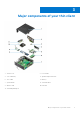
3 Major components of your thin client 1. Chassis cover 2. PCIe module 3. Coin-cell battery 4. Speaker and power button 5. CAC reader 6. Memory 7. System board 8. Solid-state drive 9. Wireless card 10. Heat sink 11.
4 Supported system peripherals for Wyse 5070 thin client This section contains details on the supported system peripherals that are shipped as part of Wyse 5070 thin client.
Supported mounts This section contains details on the supported mounts for Wyse 5070 thin client. ● P mount ● E mount ● U mount ● Dual VESA mount ● VESA Wall mount NOTE: Vertical stand will be shipped as part of Wyse 5070 thin client. For more information on mounts, see Dell Support. Supported system peripherals This section contains details on the supported system peripherals for Wyse 5070 thin client.
5 Setting up the thin client This section explains how to setup the Wyse 5070 extended thin client on premise. The Wyse 5070 extended thin client can be setup with any one of the operating systems at your work place: ● ThinOS ● Windows 10 IoT Enterprise ● ThinLinux To set up the Wyse 5070 extended thin client, do the following: 1. Install the stand. Figure 2. Install the stand 2. Connect the keyboard and mouse.
Figure 3. Install keyboard and mouse 3. Connect the network cable. Figure 4. Connect the network cable 4. Connect the display and press the power button. NOTE: The Wyse 5070 thin client must be mounted only on a vertical orientation.
Figure 5. Connect the display 5. Connect the power cable and route the power cable through the cable clip, and press the power button.
Figure 6.
6 Before working on your thin client You must perform the below steps before you work on the thin client. NOTE: For more safety best practices, see the Regulatory Compliance home page at www.dell.com/regulatory-compliance. 1. Save and close all open files and exit all open applications. 2. Click Start > Power > Shut down to shut down your thin client. NOTE: For shut down instructions, see documentation of the respective operating system. 3.
7 After working on your thin client NOTE: You must not leave the stray or loose the screws inside your thin client. This may damage your thin client. 1. Reinstall all the screws and ensure that no stray screws remain inside your thin client. 2. Connect any external devices, peripherals, or cables you removed before working on your thin client. 3. Connect your thin client and all attached devices to their electrical outlets. 4. Turn on your thin client.
8 Removing and installing components This section provides detailed information about how to remove or install the chassis and memory module of your thin client. Topics: • • • • Chassis cover PCIe module CAC reader Memory Chassis cover Chassis cover provides security for the entire thin client and also helps in maintaining proper air flow inside the thin client. Remove the chassis cover Procedure 1. Follow the procedure in Before working inside your thin client. 2.
Figure 7. Loosen the thumb screw 3. Slide the cover towards the front of the system to disengage the tabs from the guide slots on the thin client.
Figure 8. Slide the cover 4. Lift the cover away from the thin client.
Figure 9. Lift the cover Install the chassis cover Procedure 1. Align the tabs on the chassis cover with the guide slots on the thin client.
Figure 10. Align the tabs 2. Slide the cover until the tabs snap into place.
Figure 11. Slide the cover 3. Tighten the thumb screw to secure the chassis cover to the thin client.
Figure 12. Tighten the thumb screw 4. Follow the procedure in After working inside your thin client. PCIe module The PCIe module is a high-speed serial replacement of the older PCI/PCI-X bus. PCIe uses a shared parallel bus architecture, in which the PCI host and all devices share a common set of address, data, and control lines. Remove the PCIe module Prerequisites Remove the Chassis cover. Procedure 1. Follow the procedure in Before working inside your thin client. 2.
Figure 13.
Figure 14. PCIe module is removed Install the PCIe module Procedure 1. Align the PCIe module with the connector on the system board.
Figure 15. Align the PCIe module 2. Push down the PCIe module to secure it to the system board.
Figure 16. Push down the PCIe module 3. Follow the procedure in After working inside your thin client. Postrequisites Replace the Chassis cover. CAC reader CAC reader enables to read the smart card for multi factor authentication. Remove the CAC reader Prerequisites 1. Remove the Chassis cover. 2. If applicable, remove the PCIe module. Procedure 1. Follow the procedure in Before working inside your thin client. 2. Disconnect the CAC reader cable from the system board.
Figure 17. Disconnect the cable 3. Remove the two screws 1 and 2 that secure the CAC reader bracket to the system board and the chassis.
Figure 18. Remove the screws 4. Lift the CAC reader bracket away from the system board.
Figure 19. CAC reader is removed Install the CAC reader Procedure 1. Align the screw holes on the CAC reader bracket with the screw holes on the system board and chassis. 2. Replace the two screws that secure the CAC reader bracket to the system board and the chassis.
Figure 20. Align the screw holes and replace the screws 3. Connect the CAC reader cable to the system board.
Figure 21. Connect CAC cable 4. Follow the procedure in After working inside your thin client. Postrequisites 1. If applicable, replace the PCIe module. 2. Replace the Chassis cover. Memory A memory module is a circuit board that contains DRAM-integrated circuits that are installed into the memory slot on a system board. Remove the memory module Prerequisites 1. Remove the Chassis cover. 2. If applicable, remove the PCIe module. 3. Remove the CAC reader.
Procedure 1. Follow the procedure in Before working inside your thin client. 2. Using your fingertips, spread apart the securing clips on each end of the memory module slot until the memory module pops up. Figure 22. Remove the memory module 3. Slide and remove the memory module from the memory module slot.
Figure 23. Memory cards are removed Install the memory module Procedure 1. Align the notch on the memory module with the tab on the memory module slot. 2. Slide the memory module firmly into the slot at an angle and gently press the memory module down until it clicks into place. NOTE: If you do not hear the click, remove the memory module and reinstall it.
Figure 24. Install memory module 3. Follow the procedure in After working inside your thin client. Postrequisites 1. Replace the CAC reader. 2. If applicable, replace the PCIe module. 3. Replace the Chassis cover.
9 Technical specifications This section provides the technical specifications of the Wyse 5070 extended thin client. Topics: • • • • • • • • • • • • • System specifications Processor Operating systems Memory specifications Storage Audio specifications Communication specifications Ports and connectors specifications Security Battery specifications AC adapter specifications Physical specifications Environment System specifications This section describes the system specifications of the thin client.
Table 2. Processor specifications (continued) Feature Intel Gemini Lake Pentium Quad Core Maximum three core burst frequency 2.7 GHz Maximum four core burst frequency 2.
Table 4. Storage specifications (continued) Feature Specification ● SATA 6.0 Gbps interface ● ATA-8 command set ● Supports Self-Monitoring, Analysis and Reporting Technology (S.M.A.R.T) ● Supports NCQ up to queue depth of 32 Connector type 75-pin SATA-based M.2 module pinout Supply voltage 3.
Table 6. Communication specifications (continued) Feature Specification 802.11a/b/g/n/ac dual band 2 x 2 MIMO Wi-Fi through CNVi interface Antenna ● Dual external antenna connected to the Wireless card ● Frequency (GHz)–2.4 and 5 Wireless options ● Intel Dual Band Wireless-AC 2x2 ● USB 2.0 interface for Bluetooth 5.0 Ports and connectors specifications This section provide details about the ports and connectors in the thin client. Table 7.
AC adapter specifications This section describes the power adapter specifications of the thin client. Table 9. AC adapter specifications Feature Specification Type 130 W Input voltage 100-240 VAC Input current (maximum) 1.8 A Input frequency 50-60 Hz Output current 6.7 A Rated output voltage 19.
10 Wyse 5070 thin client configuration on ThinOS This section provides the instructions on how to easily configure and efficiently manage Wyse 5070 thin client that runs on ThinOS. . Topics: • • • • • Introduction Configuring ThinOS using the First Boot Wizard Logging on to the Wyse 5070 thin client running Wyse ThinOS Local settings menu Configuring the printer settings Introduction Thin clients running Dell Wyse ThinOS firmware are designed solely for optimal thin client security and performance.
● To load a ThinOS configuration file from the USB drive, ensure that you create a wnos.ini file and add the file to the /wnos directory on the USB drive. Using this option, you can load packages, and wallpapers that are specified in the INI file. Plug in the USB drive to thin client, and click Yes. NOTE: Only FAT, FAT32, and ExFAT file systems on the USB disk are supported. NTFS file system is not supported. The thin client validates the configuration file in the USB drive.
● Microsoft—The broker allows you to connect to the virtual desktops using RemoteApp and Desktop connection. Enter the host name or IP address of the broker connection. ● VMware—The broker allows you to connect to the remote desktops using VMware Horizon Client. ○ Server Address—Enter the host name or IP address of the broker connection. ○ Enable theme: VMware View—Select this check box to set the ThinOS desktop theme to VMware View mode.
2. Click the Keyboard tab and set the Character Set, Keyboard Layout, Delay Before Repeat and Repeat Rate parameters. The following table explains the keyboard parameters. Table 12. Keyboard parameters Parameter Description Character Set Lists the character sets. Each character is represented by a number. The ASCII character set, for example, uses the numbers 0 through 127 to represent all English characters and special control characters.
main screen, the monitor block is highlighted with an underline, and the Main screen option is disabled for that monitor block. The Main screen option is available for other monitor blocks. NOTE: Main screen option is effective only in Span Mode and always disabled in Mirror Mode. ● Resolution—From the Resolution drop-down list, select a display resolution supported by your monitor. In Mirror Mode, the resolution list is derived from the intersection of resolutions in all connected monitors.
Configuring the ports settings To configure the ports settings: 1. From the desktop menu, click System Setup, and then click Printer. The Printer Setup dialog box is displayed. 2. Click the Ports tab, and use the following guidelines: a. Select Port— Select the required port from the list. LPT1 or LPT2 are directly connected to the USB printer.. b. Printer Name — (Required) Enter name you want displayed in your list of printers.
If the printer is attached to another thin client on your network, the entry in the LPD Hosts box is the name or address of that thin client. e. LPD Queue Name — An LPD host maintains a named queue for each supported printer. Enter the name of the queue associated with the printer to be used. This name can be different for each vendor. This is a required field, and you must ensure to add the correct queue name, as the network printer uses this name for mapping the incoming print jobs.
11 Wyse 5070 thin client on ThinLinux This section provides instructions on how to easily configure and efficiently manage Wyse 5070 thin client that runs on ThinLinux.
and the secondary monitor is on the right (monitor 2). The resolutions of the monitors are auto detected by the system by analyzing the monitor’s capabilities. 1. Click the Display tab. The Customize Your Display page is displayed. Figure 25. Display Settings 2. Select the preferred Resolution from the drop-down list. 3. Select the Rotation type from the drop-down list. ● ● ● ● Normal Right Left Upside-down 4.
Figure 26. Keyboard Preferences 1. Click the ON/OFF button to disable or enable the Key presses repeat when held down option after you log in to the session. 2. Move the slider to the left to decrease the repeated delay time of the pointer or move the slider to the right to increase the repeated delay time of the pointer. 3. Move the slider to the left to decrease the repeat rate of the pointer or move the slider to the right to increase the repeat rate of the pointer. 4.
Table 13. 2 screens per row layout Applet window placement at monitor Traverse horizontally to monitor Traverse vertically to monitor Primary monitor (Monitor 1) Monitor 2 Monitor 3 Monitor 2 Primary monitor (Monitor 1) Monitor 4 Monitor 3 Monitor 4 Monitor 5, Primary monitor (Monitor 1) Monitor 4 Monitor 3 Monitor 2, Monitor 6 Monitor 5 Monitor 6 Monitor 3 Monitor 6 Monitor 5 Monitor 4 NOTE: ○ You cannot drag the applet window diagonally across the monitors.
Figure 27. Mouse Preferences The Mouse setting page enables you to set the Mouse preferences. 1. Click Right or Left to set the primary button of the mouse. 2. Move the slider to the left to increase the speed of the pointer when double-clicked or move the slider to the right to decrease the length of double-clicked. 3. Move the slider to the left to increase the speed of the mouse pointer or move the slider to the right to decrease the speed of the mouse pointer. 4. Click Save to save your changes.
Figure 29. Add New Printer 1. Click the printer icon. The gnome-control-center printer dialog box is displayed. 2. Click Add New Printer button to include the new printer in the printers list available on the left pane. The Add a new printer window is displayed. 3. Enter the address of the printer or the text to filter results. NOTE: If a USB printer is connected, then it is displayed by default. The printer is not found if wrong address is provided or the USB is not attached. 4. Click the Add option.
12 Wyse 5070 thin client on Windows 10 IoT Enterprise This section provides the instructions on how to easily configure and efficiently manage Wyse 5070 thin client that runs on Windows 10 IoT Enterprise. Topics: • • • • • Introduction Before configuring your thin clients Automatic and manual login Keyboard and region settings Devices and printers Introduction The thin clients running Windows 10 IoT Enterprise provide access to applications, files, and network resources.
Any operation of a Dell Wyse Windows Embedded Thin Client with the write filter turned off during regular use and/or with the Windows Page file enabled will prematurely wear out your Flash/SSD storage, decrease performance and decrease the lifespan of the product. Dell is not responsible for, and will not, warrant, support, repair or replace any thin client device or component that fails to operate properly due to a failure to follow these instructions.
a. Click Additional Settings. The Customize Format window is displayed. b. Customize the settings, and click OK. 4. Click Apply, and then click OK. 5. In the Location tab, select a particular location to display additional information such as news and weather. 6. In the Administrative tab, change the language to be displayed in programs that do not support Unicode, and copy the settings. Devices and printers To add devices and printers, use the Devices and Printers window.
For information about setting up multiple monitors, see the How to Set up Multiple Monitors in Windows 10 at support.dell.com.
13 BIOS overview Topics: • • • • • • • • • • • • • • • • Accessing thin client BIOS settings System Setup overview Boot Sequence Navigation keys General screen options System Configuration screen options Video screen option Security screen options Secure Boot screen options Performance screen options Power management screen options POST behavior screen options Wireless screen option Virtualization support screen options Maintenance screen options System Logs screen option Accessing thin client BIOS settin
Boot Sequence Boot Sequence allows you to bypass the System Setup–defined boot device order and boot directly to a specific device. During the Power-on Self Test (POST), when the Dell logo appears you can: ● Access System Setup by pressing the F2 key ● Bring up the one-time boot menu by pressing the F12 key The one-time boot menu displays the devices that you can boot from including the diagnostic option.
Table 16. General screen options (continued) Option Description ● Memory Information: Displays Memory Installed, Memory Available, Memory Speed, Memory Channels Mode, Memory Technology, DIMM A Size, DIMM B Size NOTE: Since Memory Available is less than the Memory Installed, certain operating systems may not be able to use all the available memory. ● PCI information: Displays Slot details, by default Slot1 is empty.
Table 17. System Configuration options (continued) Option Description 2nd NIC (RJ-45/SFP) The second NIC (RJ-45/SFP) option controls the second onboard NIC. The options include: ● Disabled ● Enabled ● Enabled w/PXE—This option is enabled by default Parallel Port This option determines how the parallel port on the docking station operates. The options include: ● Disabled ● AT—enabled by default ● PS2 ● ECP Serial Port1 This option determines how the serial port on the docking station operates.
Table 17. System Configuration options (continued) Option Description ● Rear port Bottom Left—enabled by default ● Rear port Top Right—enabled by default ● Rear port Bottom Right—enabled by default USB PowerShare This option configures the USB PowerShare feature and allows you to charge external devices through the USB PowerShare port when system is off. This option is enabled by default. Audio This option enables or disables the integrated audio controller.
Table 19. Security screen options (continued) Option Description uppercase character and one lowercase character. The password must be at least eight characters long. Password Configuration This option enables you to specify the minimum and maximum password lengths of the administrator and system passwords. ● min-4—By default, the minimum value is set to 4. You can increase the value. ● max-32—By default, the maximum value is set to 32. You can decrease the value.
Secure Boot screen options Table 20. Secure Boot screen options Options Description Secure Boot Enable This option enables or disables the secure boot feature. By default, the Secure Boot Enable option is not set. Secure Boot Mode This option enables you to change the secure boot operation mode, modifies the behavior of secure boot to allow evaluation or enforcement of the UEFI driver signatures.
Table 21. Performance options (continued) Option Description This option is disabled by default. Intel TurboBoost This option enables you to enables or disables the Intel TurboBoost mode of the processor. The option is: Enable Intel TurboBoost—This option is enabled by default. Power management screen options Table 22. Power management options Option Description AC Recovery This option enables you to control the system’s behavior when AC power is restored after a AC power loss.
Table 22. Power management options (continued) Option Description ● LAN with PXE Boot Block Sleep The Block Sleep option blocks you from entering to sleep mode in the operating system environment. Block Sleep—This option is disabled by default. POST behavior screen options Table 23. POST behavior options Option Description Adapter Warnings This option enables or disables the system setup (BIOS) warning messages when you use certain power adapters.
Virtualization support screen options Table 25. Virtualization options Option Description Virtualization This option enables or disables the Intel Virtualization Technology. Enable Intel Virtualization Technology (default). VT for Direct I/O This option specifies whether a virtual machine monitor can utilize the additional hardware capabilities provided by Intel Virtualization Technology for Direct I/O. This option is not enabled by default. Maintenance screen options Table 26.
14 Troubleshooting your system You can troubleshoot your system using indicators like diagnostic lights, and error messages during the operation of the device. Topics: • • • Power state and LED status Power behavior Power LED error code behavior Power state and LED status Table 28. Power states and LED behavior Indicator Power LED Symptoms Description Solid white Thin client is in working—S0 state. Breathing white Thin client is in sleep—S3 state. Off Thin client is in off state.
Table 29. Power behavior (continued) AC adapter System behavior POST error message Alert—xxxxxxW AC power adapter has been detected, which is less than the recommended xxxxxxW AC adapter originally shipped. The system is unable to boot. Please connect a Dell xxxxxxW AC adapter or greater for best system performance. Press any key to shut down. Power LED error code behavior Table 30.
Table 30. Power LED error code behavior (continued) LED# of flashes Fault description 4,2 Generic POST Video Error—Old LED pattern 1110 Fault Action Comment NA Not applicable to X7 BIOS. No test case support. Example: LED# of flashes: 2,1 indicates that LED blinks two times, pauses, and then blinks once. Troubleshooting action ● Type A ○ Log the fault event. ○ Emit the LED error code pattern. ○ Repeat the LED error code pattern in a dead-loop. ● Type B ○ Log the fault event, if possible.