Dell Wyse Management Suite Version 2.
Notes, cautions, and warnings NOTE: A NOTE indicates important information that helps you make better use of your product. CAUTION: A CAUTION indicates either potential damage to hardware or loss of data and tells you how to avoid the problem. WARNING: A WARNING indicates a potential for property damage, personal injury, or death. © 2020 Dell Inc. or its subsidiaries. All rights reserved. Dell, EMC, and other trademarks are trademarks of Dell Inc. or its subsidiaries.
Contents 1 Introduction................................................................................................................................. 5 High availability overview......................................................................................................................................................5 2 High availability architecture.........................................................................................................
12 Troubleshooting........................................................................................................................
1 Introduction Wyse Management Suite is the next generation management solution and enables you to configure, monitor, manage, and optimize your Dell Wyse thin clients. This helps you to deploy and manage thin clients on a high availability set-up with improved performance. It offers advanced feature options such as cloud versus on-premises deployment, manage-from-anywhere by using a mobile application, and enhanced security such as BIOS configuration and port lockdown.
2 High availability architecture The Dell Wyse Management Suite architecture consists of Windows Server 2012 R2/2016/2019 with failover cluster enabled. The Windows cluster contains a main computer that supports other applications and ensures minimum downtime by harnessing the redundant. This is used for application failover for Tomcat, Memcache, MQTT services. MongoDB database cluster helps in the event of primary database failure the secondary database will take over.
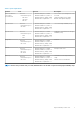
Table 1. System requirements Product Port Protocol Description Microsoft Windows Server 2012 R2/2016/2019 • • • • • Minimum disk space—40 GB Minimum number of systems—2 Minimum memory (RAM)—8 GB Minimum CPU requirements—4 Server where Wyse Management Suite is hosted. MySQL Cluster • Network communication port— TCP:3306 • • • • Minimum disk space—40 GB Minimum number of systems—3 Minimum memory (RAM)—8 GB Minimum CPU requirements—4 Server in the high availability setup.
3 High availability on Windows Server 2012 R2/2016/2019 A failover cluster is a group of independent systems that increases the availability and scalability of clustered roles. This feature supports multiple workloads running clusters on hardware or on virtual machines. A failover cluster is a group of systems that are independent and increases the availability and scalability of clustered roles. The clustered servers are the nodes that are connected to one another as a network.
3. Right-click Roles and then select Configure Role to display the High Availability Wizard screen. Figure 3. High availability wizard 4. Select Generic Service and then click Next to view the Select Service screen. Figure 4. Select service 5. Select Dell WMS: Tomcat Service and then click Next.
NOTE: You can add the Wyse Management Suite related services to the cluster only after you install Wyse Management Suite. The High Availability Wizard screen is displayed where you need to create the client access point and establish connectivity between the Windows server 2012 and Wyse Management Suite. 6. Type a network name in the Name field and then click Next. The Confirmation screen is displayed with the network name and IP address details of the server. Figure 5. Confirmation 7.
4 Achieve high availability on Windows Server 2012 R2/2016/2019 About this task The following are the steps to achieve high availability on Windows Server 2012/2016/2019: 1. Add failover cluster feature on Windows Server 2012 R2/2016/2019—see Adding failover cluster feature on Windows Server 2012 R2/2016/2019. 2. Create file share witness—see Create file share witness. 3. Configure cluster Quorum—see Configure cluster Quorum. 4. Create clustered roles—see Create cluster roles.
Figure 6. Role based selection 3. Click Installation Type and select Role-based or Feature-based installation and then click Next to view the list of servers in the Select destination server screen. Figure 7. Select server destination 4. Select the server where you want to enable the failover cluster feature and then click Next. 5. Select Failover Clustering on the Features screen, and then click Next.
6. Click Yes to confirm installation, and enable the failover cluster feature on the selected server. 7. In the Failover Cluster Manager screen, click Validate Configuration to view the Validate a Configuration Wizard add the required servers or nodes to cluster. Figure 8. Failover cluster manager 8. Click Select servers or cluster and then click Browse to configure the servers. 9. ClickNext and select Run all tests from the Testing Options screen.
Figure 9. Testing options 10. Click Next. The Confirmation screen is displayed with the list of selected servers.
Figure 10. Confirmation 11. Click Next. The Summary screen is displayed with the failover cluster validation report.
Figure 11. Test summary details 12. Click View Report to check the report. If the status is Passed, you can proceed with the next step. If the status is Failed, you must fix the errors before you proceed with the next step. NOTE: The Create Cluster Wizard screen is displayed if there are no validation errors. 13. Click Next and type a name for the cluster in the Cluster Name field and then select the IP address of the system. 14. Click Next and the Confirmation screen is displayed. 15.
8. Click Create to create the file share and the View results screen is displayed with the status as Completed which indicates that the file share witness is created without any errors. 9. Click Close to exit. Configure cluster quorum settings The cluster configuration database, also called the quorum, contains details as to which server should be active at any given time in a cluster set-up. About this task To configure the cluster quorum settings, do the following: Steps 1.
Figure 13. Select voting configuration 6. Click Next . Select Configure a file share witness from the Select Quorum Witness screen. 7. Click Next and then type the share path in the File Share Path field from the Configure a file share witness screen. Figure 14. Configure file share witness 8. Click Next . TheSummary screen is displayed with the configured quorum settings.
Figure 15. Summary of the quorum settings 9. Click Finish to complete the quorum settings. Creating clustered roles Prerequisites After you create the failover cluster, you can create clustered roles to host cluster workloads. Ensure that Wyse Management Suite is installed on the servers and point to the remote database before you create clustered roles. Steps 1. In Windows Server 2012, right-click the Start menu and then select Server Manager to launch the Server Manager dashboard 2.
Figure 16. High availability wizard 4. Select Generic Service and then click Next to view the Select Service screen. Figure 17. Select service 5. Select Dell WMS: Tomcat Service and then click Next. NOTE: You can add the Wyse Management Suite related services to the cluster only after you install Wyse Management Suite.
The High Availability Wizard screen is displayed where you need to create the client access point and establish connectivity between the Windows server 2012 and Wyse Management Suite. 6. Type a network name in the Name field and then click Next. The Confirmation screen is displayed with the network name and IP address details of the server. Figure 18. Confirmation 7. Click Next to complete the process. 8.
5 Achieve high availability for MySQL InnoDB About this task The following steps explain how to achieve high availability for MySQL InnoDB: Steps 1. Check MySQL InnoDB server instance—see Create MySQL InnoDB cluster. 2. Add server or node to MySQL InnoDB—see Adding server or node to MySQL InnoDB cluster. 3. Create MySQL Router—see Creating MySQL Router High availability with MySQL InnoDB The MySQL InnoDB cluster provides a complete high availability solution for MySQL.
Figure 19. Setup type 4. On the Select Products and Features screen, select the MySQL Server, workbench, and shell components, and click Next.
Figure 20. Products and features 5. On the Check Requirements screen, select the components, and click Execute.
Figure 21. Requirements 6. Install the required components, and click Next.
Figure 22.
Figure 23. Requirements 7. On the Installation screen, click Execute.
Figure 24. Installation The MySQL server, workbench, and shell components are upgraded. 8. Click Next.
Figure 25. Installation 9. On the Product Configuration screen, the MySQL server component is displayed.
Figure 26. Product configuration 10. Click Next to configure the MySQL server component. 11. On the Group Replication screen, click the Standalone MySQL Server / Classic MySQL Replication radio button, and click Next.
Figure 27. Group replication 12. On the Type and Networking screen, select the Dedicated Computer option from the Config Type drop-down list.
Figure 28. Type and networking 13. Select and configure the options in the Connectivity section, and click Next. 14. In the Accounts and Roles screen, enter the MySQL root password. 15. Click Add User.
Figure 29. Add user The MySQL User Details window is displayed. 16. Enter the credentials and click Ok. The newly added user account is displayed in the MySQL User Accounts section.
Figure 30. Accounts and roles 17. Click Next. 18. On the Windows Service screen, enter the MySQL Windows service name, and click Next.
Figure 31. Windows service 19. On the Plugins and Extensions screen, click Next.
Figure 32. Plugins and extensions 20. On the Apply Configuration screen, click Execute. The configurations are applied to the MySQL component.
Figure 33. Apply configurations 21. Click Finish.
Figure 34. Apply configurations 22. On the Product Configuration screen, click Next.
Figure 35. Product configuration 23. On the Installation Complete screen, click Finish.
Figure 36. Installation complete Next steps Follow the procedure to install and configure MySQL server in all the three servers of the MySQL cluster. NOTE: To set up the environment as per the high availability setup, see dev.mysql.com. Check MySQL InnoDB server instances About this task Before you add MySQL InnoDB to the cluster setup, verify that MySQL InnoDB is created as per the cluster requirements.
Figure 37. MySQL command prompt • • • To check that the MySQL InnoDB is created on all the three cluster nodes, run the following commands at the command prompt: mysql-js> dba.checkInstanceConfiguration('root@IPAddress1:3306') mysql-js> dba.checkInstanceConfiguration('root@IPAddress2:3306') mysql-js> dba.checkInstanceConfiguration('root@IPAddress3:3306') The instance "IPAddress:3306" is valid for InnoDB cluster usage; 'Status': 'ok' message is displayed.
Figure 39. Confirmation screen Add server instance to MySQL InnoDB cluster Prerequisites • • Before you add servers or nodes to the clusters, change the server id to either 2 or 3 in the my.conf file in the secondary MySQL servers at C:\ProgramData\MySQL\MySQL Server 5.7. Only the primary MySQL server must have server ID as 1. The server ID should be unique across the SQL cluster. About this task You must add server instance to the MySQL InnoDB cluster as primary or secondary.
Figure 40. Cluster status Configure MySQL Router Prerequisites MySQL Router establishes communication network between Wyse Management Suite and MySQL InnoDB. About this task To install MySQL Router, do the following: Steps 1. Log in to the Windows Server 2012/2016 to install MySQL Router. For more information, see MySQL Router Installation 2. Select MySQL Router from the Select Products and Features screen and then click Next .
Figure 41. Select products and features 3. On the Check Requirements screen, click Execute.
Figure 42. Check requirements 4. Install the required components, and click Next.
Figure 43.
Figure 44. Check requirements 5. On the Installation screen, click Execute.
Figure 45. Installation MySQL router component is upgraded. 6. Click Next.
Figure 46. Installation 7. On the Product Configuration screen, the MySQL router component is displayed.
Figure 47. Product configuration 8. Click Next to configure the MySQL router component. 9. On the MySQL Router Configuration screen, enter the hostname, port number, management user, and password.
Figure 48. MySQL Router Configuration 10. On the Apply Configuration screen, click Execute.
Figure 49. Apply configuration 11. Click Finish.
Figure 50. Apply configurations 12. On the Product Configuration screen, click Next.
Figure 51. Product configuration The Installation Complete message is displayed.
Figure 52. Installation complete 13. Click Finish. 14. Browse to \ProgramData\MySQL\MySQL Router directory, and open the file mysqlrouter.conf to check that the bootstrap property with all the configured MySQL servers are part of cluster setup.
Figure 53. Bootstrap server address Create database and users on MySQL InnoDB server You must create the database and user accounts with administrator privileges on MySQL InnoDB server.
6 Achieve high availability on MongoDB About this task The following steps explain how to achieve high availability on MongoDB: Steps 1. Install MongoDB—see Installing MongoDB. 2. Create replica servers—see Creating Replica servers. 3. Create Stratus users—see Creating Stratus user account. 4. Create root user—see Creating root user for MongoDB. 5. Edit MongoDB configuration file—see Editing MongoDB configuration file.
Figure 55. mongod.cfg file 4. Open the mongod.cfg file in a text editor, and add: systemLog: destination: file path: c:\data\log\mongod.log storage: dbPath: c:\data\db 5. Save the file. 6. Open command prompt. 7. Run the following command to start the MongoDB service: a) C:\MongoDB\bin>.\mongod.exe --config c:\Mongodb\mongod.cfg --install b) C:\MongoDB\bin>net start mongodb The message MongoDB service is starting is displayed. 8. Change the working directory to \MongoDB\bin. 9. Run Mongo.
Create database user Create an user, for example, DBUser using the Wyse Management Suite to access MongoDB. NOTE: The database user and password are examples and can be created using a different name and password at your work place. Run the following command to create the DBUser: db.
net: bindIp: x.x.x.x, 0.0.0.0 port: 27017 security: authorization: enabled NOTE: The port numbers will change depending on the system at the work place. 4. Save mongod.cfg and exit. Initiate replication on the servers Ensure that you disable firewall on Windows and stop Tomcat servers if they are running. 1. Login to MongoDB as root user that you have already created and run the following command: mongo -uroot - admin 2. Go to \data\bin\mongod.cfg directory, and open mongod.
Figure 58. Copy the mongod key file 5. After you copy the file, stop the mongod service by running the following command: net stop mongodb 6. Start the mongod service by running the following command: net start mongodb 7. Repeat the steps from 1 to 6 in all the three nodes of MongoDB servers. 8. Initiate replication on the primary node of the MongoDB cluster logging in using DBadmin user and then run the following command: rs.initiate(); C:\Mongo\bin>mongo.exe -u root -p x` admin MongoDB shell version v4.2.
Figure 59. Replication status 10. Start mongod service and add the secondary nodes to the second and third nodes in the MongoDB cluster: rs.add("IPAddress2:27017") rs.add("IPAddress3:27017") MongoDB Enterprise wms20:PRIMARY> rs.add("10.150.132.
Figure 60. Status in primary server Figure 61.
7 Achieve high availability for Teradici devices Wyse Management Suite uses the HAProxy hosted on the Ubuntu server 16.04.1 LTS to perform load balancing between the EMSDK servers. HAProxy is a load balancer proxy that can also provide high availability based on how it is configured. It is a popular open source software for TCP/HTTP Load Balancer, and proxy solution which runs on Linux operating system.
The following text is a sample HAProxy configuration file: global log /dev/log local0 log /dev/log local1 notice chroot /var/lib/haproxy daemon #maxconn is maximum allowed connections maxconn 60000 defaults log global mode tcp timeout connect 5000ms timeout client 50000ms timeout server 50000ms errorfile 400 /etc/haproxy/errors/400.http errorfile 403 /etc/haproxy/errors/403.http errorfile 408 /etc/haproxy/errors/408.http errorfile 500 /etc/haproxy/errors/500.http errorfile 502 /etc/haproxy/errors/502.
8 Install Wyse Management Suite on Windows Server 2012 R2/2016/2019 Prerequisites Ensure that the following servers are configured before installation of Wyse Management Suite application: • • • • Windows Fail over Cluster on Two Nodes MongoDB Server Running with replica set MySQL Server InnoDB Cluster up running MySQL Router installed on the two Nodes About this task Installation of Wyse Management Suite 1.3 or higher on both the Nodes in Windows Cluster Steps 1.
Figure 64. Configuration 4. Select the External MariaDB option for MySQL. Provide MySQL router address (Local Host if it is installed on Wyse Management Suite server node) in the External Maria DB Server fields with the port number(Default 6446). You must type the MySQL database user account information that was created initially. NOTE: Ensure that the "Stratus" Database is created and "DB User" account(stratus) with appropriate Privileges is created on MySQL server.
Figure 66. Database command d. Execute following commands to create and Stratus User account and privileges: • Create user 'stratus'@'localhost' • Create user 'stratus'@'10.150.132.21' • Set password for 'stratus'@'localhost' = password ('PASSWORD') • Set password for 'stratus'@'IP ADDRESS'= password ('PASSWORD') • Grant all privileges on *.* to 'stratus'@'IP ADDRESS' identified by 'PASSWORD' with grant option. • Grant all privileges on *.
Figure 69. Configuration 6. Provide administrator credentials and email address information. Figure 70. Configuration 7. Provide Teradici EM SDK Port information and CIFS User Account information.
Figure 71. Teradici EM SDK 8. Provide ‘Destination Installation folder path’ and ‘Shared UNC path’ for Local repository. Figure 72. Destination 9. Recheck the Installation Summary information before we proceed with the Wyse Management Suite installation. 10. Complete the Installation on both the nodes. Type the Destination Installation folder path and Shared UNC path for the local repository and then click Next. The message The installation was successful is displayed.
After 'Data' folder is deleted from the shared UNC WMS Local Repository path, you can install Wyse Management Suite Application in the Node 2 of the Windows Cluster. Figure 73.
9 Post installation checks About this task Do the following to check the high availability for Wyse Management Suite: • • Launch the Wyse Management Suite administrator portal and check whether you can log in using the web interface. Edit the bootstrap.properties file in the Tomcat server under the \Dell\WMS\Tomcat-9\webapps\ccm-web\WEB-INF \classes folder for MongoDB as follows: mongodb.
10 Upgrade Wyse Management Suite version 1.3 to 1.4 Prerequisites • • Ensure that the mongodb.seedList value in the bootstrap.properties file includes backslash character (\) in the list of Mongo database servers. The bootstrap.properties file is at Tomcat-9\webapps\ccm-web\WEB-INF\classes, mongodb.seedList = MongoDBServer1_IP\:27017, MongoDBServer2_IP\:27017, MongoDBServer3_IP \:27017. Figure 74.
Figure 75. Welcome screen 3. On the Upgrade page, click Next to upgrade Wyse Management Suite . 74 Upgrade Wyse Management Suite version 1.3 to 1.
Figure 76. Upgrade Upgrade Wyse Management Suite version 1.3 to 1.
Figure 77. Upgrade 4. Click Launch to open the Wyse Management Suite web console. 76 Upgrade Wyse Management Suite version 1.3 to 1.
Figure 78. Launch Next steps • Ensure that Tomcat-8 folder and subfolders are deleted, and Tomcat-9 folder and subfolders are created. Also, do the following: • • • • Ensure that Tomcat-9\webapps\ccm-web\WEB-INF\classes folders and subfolders are created. Ensure that Tomcat-9 service is added, and Tomcat-9 service is running. Ensure that the bootstrap.properties file is copied from Tomcat-8\ webapps\ccm-web\WEB-INF\classes folder to Tomcat-9\webapps\ccm-web\WEB-INF\classes folder.
Figure 79. Access point 3. Check the version of the Tomcat service. If the version of the Tomcat service is 8, you must manually remove Tomcat‐ 8 and add Tomcat‐9 service into the Access Point. This is because, when you upgrade Wyse Management Suite 1.4 to WMS 2.0, Tomcat‐8 service is replaced with Tomcat‐9. 4. Right-click the Tomcat-8 service, and then click Remove. Figure 80. Tomcat service removal 5. Add the Tomcat-9 service to the access point. 78 Upgrade Wyse Management Suite version 1.3 to 1.
Figure 81. Tomcat-9 service Figure 82. Tomcat 9 service 6. Bind the FQDN address of the access point of High Availability to the Memcached registry on both nodes of the High Availability setup using the command Registry Path: HKLM\SYSTEM\CurrentControlSet\Services\Memcached\ “ImagePath” = “C:\Program Files\DELL\WMS\memcached\memcached.exe" -d runservice -p -I 11211 WMS1314AP.AD132.COM -U 0” Upgrade Wyse Management Suite version 1.3 to 1.
Figure 83. Memcached data 80 Upgrade Wyse Management Suite version 1.3 to 1.
11 Upgrading from Wyse Management Suite version1.4/1.4.1 to Wyse Management Suite version 2.0 Prerequisites Ensure to perform the following tasks before upgrading to Wyse Management Suite version 2.0. • • Set the policy of the resources(tomcat,memcache,mqtt) in the access point to "if resource fails, Do not restart" though default policy “if resource fails, attempt restart on current node ” is recommended, for failover scenario it does not allow the product to upgrade. Figure 84.
Figure 85. Upgrade 3. Select the Bind Memcached to 127.0.0.1 check box to bind the memcache to local server—127.0.0.1. If this check box is not selected, the memcache is binded to FQDN. Figure 86. Teradici EM SDK 4. Click Next. 82 Upgrading from Wyse Management Suite version1.4/1.4.1 to Wyse Management Suite version 2.
Figure 87. Upgrade 5. In the Dell Wyse Management Suite - InstallShield Wizard window, click Yes. Figure 88. Upgrade Wait for the installation to complete. Figure 89. Upgrade Upgrading from Wyse Management Suite version1.4/1.4.1 to Wyse Management Suite version 2.
Figure 90. Upgrade Figure 91. Upgrade Figure 92. Upgrade Post upgrade from Wyse Management Suite version1.4/1.4.1 to Wyse Management Suite version 2.0 Ensure to change back the Access Point’s service policy setting of the resources to default “if resource fails, attempt restart on current node ” configuration. 84 Upgrading from Wyse Management Suite version1.4/1.4.1 to Wyse Management Suite version 2.
Figure 93. Access point Upgrading from Wyse Management Suite version1.4/1.4.1 to Wyse Management Suite version 2.
12 Troubleshooting About this task This section provides troubleshooting information for Wyse Management Suite version 1.x for the cluster set up. • Problem: Where is the Wyse Management Suite log file located to check server installation issues. • Workaround: The log file is in the %temp% WMSInstall.logfolder. Problem: Where is the Tomcat service related log file located to check the application related issues.
Figure 94. Error message Workaround: Change the server ID entries in the my.conf file located in the \ProgramData\MySQL\MySQL Server 5.7 directory. Figure 95.