Dell Wyse Management Suite Version 1.
Notes, cautions, and warnings NOTE: A NOTE indicates important information that helps you make better use of your product. CAUTION: A CAUTION indicates either potential damage to hardware or loss of data and tells you how to avoid the problem. WARNING: A WARNING indicates a potential for property damage, personal injury, or death. © 2019 Dell Inc. or its subsidiaries. All rights reserved. Dell, EMC, and other trademarks are trademarks of Dell Inc. or its subsidiaries.
Contents 1 Introduction....................................................................................................................................................4 High availability overview.................................................................................................................................................. 4 2 High availability architecture..........................................................................................................................
1 Introduction Wyse Management Suite version 1.4 is the next generation management solution and enables you to configure, monitor, manage, and optimize your Dell Wyse thin clients. This helps you to deploy and manage thin clients on a high availability set-up with improved performance. It offers advanced feature options such as cloud versus on-premises deployment, manage-from-anywhere by using a mobile application, and enhanced security such as BIOS configuration and port lockdown.
2 High availability architecture The Dell Wyse Management Suite architecture consists of Windows Server 2012/2016 with failover cluster enabled. The Windows cluster contains a main computer that supports other applications and ensures minimum downtime by harnessing the redundant. This is used for application failover for Tomcat, Memcache, MQTT services. MongoDB database cluster helps in the event of primary database failure the secondary database will take over.
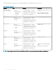
The hardware and software requirements to set up high availability for Wyse Management Suite version 1.4 are: Table 1. System requirements Product Port Protocol Description Microsoft Windows Server 2012/2016 R2 • • Minimum disk space—40 GB • Minimum number of systems—2 Server where Wyse Management Suite is hosted.
3 High availability on Windows Server 2012/2016 A failover cluster is a group of independent systems that increases the availability and scalability of clustered roles. This feature supports multiple workloads running clusters on hardware or on virtual machines. A failover cluster is a group of systems that are independent and increases the availability and scalability of clustered roles. The clustered servers are the nodes that are connected to one another as a network.
Steps 1 In Microsoft Windows Server 2012, right-click the Start menu and then select Server Manager to launch the Server Manager dashboard 2 Click Failover Cluster Manager to launch the cluster manager. 3 Right-click Roles and then select Configure Role to display the High Availability Wizard screen. Figure 3. High availability wizard 4 Select Generic Service and then click Next to view the Select Service screen.
Figure 4. Select service 5 Select Dell WMS: Tomcat Service and then click Next. NOTE: You can add the Wyse Management Suite version 1.4 related services to the cluster only after you install Wyse Management Suite version 1.4. The High Availability Wizard screen is displayed where you need to create the client access point and establish connectivity between the Windows server 2012 and Wyse Management Suite. 6 Type a network name in the Name field and then click Next.
Figure 5. Confirmation 7 Click Next to complete the process. 8 To add other Wyse Management Suite services as part of the cluster, launch Failover Cluster Manager, and then go to ActionsRoles to display the network name that you have created. 9 Click on the network name, and go to Add ResourceGeneric Service.
4 Achieve high availability on Windows Server 2012/2016 The following are the steps to achieve high availability on Windows Server 2012/2016: 1 Add failover cluster feature on Windows Server 2012/2016—see Adding failover cluster feature on Windows Server 2012/2016. 2 Create file share witness—see Create file share witness. 3 Configure cluster Quorum—see Configure cluster Quorum. 4 Create clustered roles—see Create cluster roles.
Figure 6. Role based selection 3 Click Installation Type and select Role-based or Feature-based installation and then click Next to view the list of servers in the Select destination server screen.
Figure 7. Select server destination 4 Select the server where you want to enable the failover cluster feature and then click Next. 5 Select Failover Clustering on the Features screen, and then click Next. After you enable the failover cluster on the servers, open the Failover Cluster Manager on the server at Node 1. 6 Click Yes to confirm installation, and enable the failover cluster feature on the selected server.
Figure 8. Failover cluster manager 8 Click Select servers or cluster and then click Browse to configure the servers. 9 ClickNext and select Run all tests from the Testing Options screen.
Figure 9. Testing options 10 Click Next. The Confirmation screen is displayed with the list of selected servers.
Figure 10. Confirmation 11 Click Next. The Summary screen is displayed with the failover cluster validation report.
Figure 11. Test summary details 12 Click View Report to check the report. If the status is Passed, you can proceed with the next step. If the status is Failed, you must fix the errors before you proceed with the next step. NOTE: The Create Cluster Wizard screen is displayed if there are no validation errors. 13 Click Next and type a name for the cluster in the Cluster Name field and then select the IP address of the system. 14 Click Next and the Confirmation screen is displayed.
8 Click Create to create the file share and the View results screen is displayed with the status as Completed which indicates that the file share witness is created without any errors. 9 Click Close to exit. Configure cluster quorum settings The cluster configuration database, also called the quorum, contains details as to which server should be active at any given time in a cluster set-up.
Figure 13. Select voting configuration 6 Click Next . Select Configure a file share witness from the Select Quorum Witness screen. 7 Click Next and then type the share path in the File Share Path field from the Configure a file share witness screen. Figure 14. Configure file share witness 8 Click Next . TheSummary screen is displayed with the configured quorum settings.
Figure 15. Summary of the quorum settings 9 Click Finish to complete the quorum settings. Creating clustered roles Prerequisite After you create the failover cluster, you can create clustered roles to host cluster workloads. Ensure that Wyse Management Suite is installed on the servers and point to the remote database before you create clustered roles.
Figure 16. High availability wizard 4 Select Generic Service and then click Next to view the Select Service screen.
Figure 17. Select service 5 Select Dell WMS: Tomcat Service and then click Next. NOTE: You can add the Wyse Management Suite version 1.4 related services to the cluster only after you install Wyse Management Suite version 1.4. The High Availability Wizard screen is displayed where you need to create the client access point and establish connectivity between the Windows server 2012 and Wyse Management Suite. 6 Type a network name in the Name field and then click Next.
Figure 18. Confirmation 7 Click Next to complete the process. 8 To add other Wyse Management Suite services as part of the cluster, launch Failover Cluster Manager, and then go to ActionsRoles to display the network name that you have created. 9 Click on the network name, and go to Add ResourceGeneric Service.
5 Achieve high availability for MySQL InnoDB About this task The following steps explain how to achieve high availability for MySQL InnoDB: Steps 1 Check MySQL InnoDB server instance—see Create MySQL InnoDB cluster. 2 Add server or node to MySQL InnoDB—see Adding server or node to MySQL InnoDB cluster. 3 Create MySQL Router—see Creating MySQL Router High availability with MySQL InnoDB The MySQL InnoDB cluster provides a complete high availability solution for MySQL.
Figure 19. Setup type 4 On the Select Products and Features screen, select the MySQL Server, workbench, and shell components, and click Next.
Figure 20. Products and features 5 On the Check Requirements screen, select the components, and click Execute.
Figure 21. Requirements 6 Install the required components, and click Next.
Figure 22.
Figure 23. Requirements 7 On the Installation screen, click Execute.
Figure 24. Installation The MySQL server, workbench, and shell components are upgraded. 8 Click Next.
Figure 25. Installation 9 On the Product Configuration screen, the MySQL server component is displayed.
Figure 26. Product configuration 10 Click Next to configure the MySQL server component. 11 On the Group Replication screen, click the Standalone MySQL Server / Classic MySQL Replication radio button, and click Next.
Figure 27. Group replication 12 On the Type and Networking screen, select the Dedicated Computer option from the Config Type drop-down list.
Figure 28. Type and networking 13 Select and configure the options in the Connectivity section, and click Next. 14 In the Accounts and Roles screen, enter the MySQL root password. 15 Click Add User.
Figure 29. Add user The MySQL User Details window is displayed. 16 Enter the credentials and click Ok. The newly added user account is displayed in the MySQL User Accounts section.
Figure 30. Accounts and roles 17 Click Next. 18 On the Windows Service screen, enter the MySQL Windows service name, and click Next.
Figure 31. Windows service 19 On the Plugins and Extensions screen, click Next.
Figure 32. Plugins and extensions 20 On the Apply Configuration screen, click Execute. The configurations are applied to the MySQL component.
Figure 33. Apply configurations 21 Click Finish.
Figure 34. Apply configurations 22 On the Product Configuration screen, click Next.
Figure 35. Product configuration 23 On the Installation Complete screen, click Finish.
Figure 36. Installation complete Next step Follow the procedure to install and configure MySQL server in all the three servers of the MySQL cluster. NOTE: To set up the environment as per the high availability setup, see dev.mysql.com. Check MySQL InnoDB server instances Before you add MySQL InnoDB to the cluster setup, verify that MySQL InnoDB is created as per the cluster requirements. You must login as root user to run the commands and restart the system each time you run a set of commands.
Figure 37. MySQL command prompt • • • To check that the MySQL InnoDB is created on all the three cluster nodes, run the following commands at the command prompt: mysql-js> dba.checkInstanceConfiguration('root@IPAddress1:3306') mysql-js> dba.checkInstanceConfiguration('root@IPAddress2:3306') mysql-js> dba.checkInstanceConfiguration('root@IPAddress3:3306') The instance "IPAddress:3306" is valid for InnoDB cluster usage; 'Status': 'ok' message is displayed.
MySql JS>Cluster.status() The status of the created cluster is displayed as ONLINE which indicates that the cluster is created successfully. Figure 39. Confirmation screen Add server instance to MySQL InnoDB cluster Prerequisite • Before you add servers or nodes to the clusters, change the server id to either 2 or 3 in the my.conf file in the secondary MySQL servers at C:\ProgramData\MySQL\MySQL Server 5.7. • Only the primary MySQL server must have server ID as 1.
Figure 40. Cluster status Configure MySQL Router Prerequisite MySQL Router establishes communication network between Wyse Management Suite and MySQL InnoDB. About this task To install MySQL Router, do the following: Steps 1 Log in to the Windows Server 2012/2016 to install MySQL Router. For more information, see MySQL Router Installation 2 Select MySQL Router from the Select Products and Features screen and then click Next .
Figure 41. Select products and features 3 On the Check Requirements screen, click Execute.
Figure 42. Check requirements 4 Install the required components, and click Next.
Figure 43.
Figure 44. Check requirements 5 On the Installation screen, click Execute.
Figure 45. Installation MySQL router component is upgraded. 6 Click Next.
Figure 46. Installation 7 On the Product Configuration screen, the MySQL router component is displayed.
Figure 47. Product configuration 8 Click Next to configure the MySQL router component. 9 On the MySQL Router Configuration screen, enter the hostname, port number, management user, and password.
Figure 48. MySQL Router Configuration 10 On the Apply Configuration screen, click Execute.
Figure 49. Apply configuration 11 Click Finish.
Figure 50. Apply configurations 12 On the Product Configuration screen, click Next.
Figure 51. Product configuration The Installation Complete message is displayed.
Figure 52. Installation complete 13 Click Finish. 14 Browse to \ProgramData\MySQL\MySQL Router directory, and open the file mysqlrouter.conf to check that the bootstrap property with all the configured MySQL servers are part of cluster setup.
Figure 53. Bootstrap server address Create database and users on MySQL InnoDB server You must create the database and user accounts with administrator privileges on MySQL InnoDB server.
6 Achieve high availability on MongoDB About this task The following steps explain how to achieve high availability on MongoDB: Steps 1 Install MongoDB—see Installing MongoDB. 2 Create replica servers—see Creating Replica servers. 3 Create Stratus users—see Creating Stratus user account. 4 Create root user—see Creating root user for MongoDB. 5 Edit MongoDB configuration file—see Editing MongoDB configuration file.
Figure 55. mongod.cfg file 4 Open the mongod.cfg file in a text editor, and add the following entries: a b c SystemLog:destination: file path: c:\data\log\mongod.log Storage: dbpath: c:\data\db 5 Save the file. 6 Open command prompt. 7 Run the following command to start the MongoDB service: a b C:\MongoDB\bin>.\mongod.exe --config c:\Mongodb\mongod.cfg --install C:\MongoDB\bin>net start mongodb The message MongoDB service is starting is displayed. 8 Change the working directory to \MongoDB\bin.
Create DBadmin user for MongoDB Login to the MongoDB using the user account created in the previous section. The DBadmin user is created with the administrative privileges. Run the following command to create the DBadmin user: mongo -uDBUser -pPassword admin use admin db.createUser( { user: "DBadmin", pwd: , roles: [ { role: "DBadmin", db: "admin" } ] }) Edit mongod.cfg file You must edit the mongod.cfg file to enable the security for the MongoDB database.
2 Go to \data\bin\mongod.cfg directory, and open mongod.cfg file in a text editor. 3 Add the following three lines in the mongod.cfg file: keyFile: c:\data\log\mongod.key.txt replication: replSetName: wms Figure 57. Enabling security 4 Create mongod.key.txt file and copy on all the three servers. NOTE: Ensure that the mongod.key.txt file content or key is the same in all the three servers. Figure 58.
9 Check the replication status by running the following command: rs.status(); Figure 59. Replication status 10 Start mongod service and add the secondary nodes to the second and third nodes in the MongoDB cluster: rs.add("IPAddress2:27017") rs.add("IPAddress3:27017") NOTE: The port numbers will differ based on the systems at your network and systems. 11 After you add the nodes in the MongoDB cluster, check the replication status by running the following commands for the primary and secondary nodes: rs.
Figure 60. Status in primary server Figure 61.
7 Achieve high availability for Teradici devices Wyse Management Suite uses the HAProxy hosted on the Ubuntu server 16.04.1 LTS to perform load balancing between the EMSDK servers. HAProxy is a load balancer proxy that can also provide high availability based on how it is configured. It is a popular open source software for TCP/HTTP Load Balancer, and proxy solution which runs on Linux operating system.
NOTE: Administrator must add additional back end servers beyond the total number of client’s capacity to have seamless failover. 5 Save the changes to the haproxy.cfg file by typing CTRL+O.
Install Wyse Management Suite server Ensure that the following components are configured before you install Wyse Management Suite server: • Windows Failover Cluster on two Nodes • MongoDB Server is running with replica set • MySQL InnoDB Cluster set-up is running • MySQL Router isinstalled on the two Nodes Do the following to install Wyse Management Suite server: 1 Launch the Wyse Management Suite installer screen. 2 Select Custom Type and Teradici EMSDK and then click Next.
8 Install Wyse Management Suite on Windows Server 2012/2016 About this task To install the Wyse Management Suite on a private cloud, do the following: Steps 1 Double-click the installer package. 2 On the Welcome screen, read the license agreement, and click Next. 3 Select the Setup Type you want to install, and click Next. The available options are: 4 • Typical—Requires minimum user interaction and installs embedded databases.
9 Upgrade Wyse Management Suite version 1.3 to 1.4 Prerequisites • Ensure that the mongodb.seedList value in the bootstrap.properties file includes backslash character (\) in the list of Mongo database servers. The bootstrap.properties file is at Tomcat-8\webapps\ccm-web\WEB-INF\classes, mongodb.seedList = MongoDBServer1_IP\:27017, MongoDBServer2_IP\:27017, MongoDBServer3_IP\:27017. Figure 62.
Figure 63. Welcome screen 3 On the Upgrade page, click Next to upgrade Wyse Management Suite . 70 Upgrade Wyse Management Suite version 1.3 to 1.
Figure 64. Upgrade Upgrade Wyse Management Suite version 1.3 to 1.
Figure 65. Upgrade 4 Click Launch to open the Wyse Management Suite web console. 72 Upgrade Wyse Management Suite version 1.3 to 1.
Figure 66. Launch Next steps • Ensure that Tomcat-8 folder and subfolders are deleted, and Tomcat-9 folder and subfolders are created. Also, do the following: – Ensure that Tomcat-9\webapps\ccm-web\WEB-INF\classes folders and subfolders are created. – Ensure that Tomcat-9 service is added, and Tomcat-9 service is running. – Ensure that the bootstrap.properties file is copied from Tomcat-8\ webapps\ccm-web\WEB-INF\classes folder to Tomcat-9\webapps\ccm-web\WEB-INF\classes folder. – Ensure that the mongodb.
Figure 67. Access point c Check the version of the Tomcat service. If the version of the Tomcat service is 8, you must manually remove Tomcat‐ 8 and add Tomcat‐9 service into the Access Point.This is because, when you upgrade Wyse Management Suite 1.3 to WMS 1.4, Tomcat‐8 service is replaced with Tomcat‐9. d Right-click the Tomcat-8 service, and then click Remove. Figure 68. Tomcat service removal e 74 Add the Tomcat-9 service to the access point. Upgrade Wyse Management Suite version 1.3 to 1.
Figure 69. Tomcat-9 service Figure 70. Tomcat 9 service f Bind the FQDN adress of the access point of High Availability to the Memcached registry on both nodes of the High Availability setup using the command Registry Path: HKLM\SYSTEM\CurrentControlSet\Services\Memcached\ “ImagePath” = “C:\Program Files\DELL\WMS\memcached\memcached.exe" -d runservice -p -I 11211 WMS1314AP.AD132.COM -U 0” Upgrade Wyse Management Suite version 1.3 to 1.
Figure 71. Memcached data 76 Upgrade Wyse Management Suite version 1.3 to 1.
10 Post installation checks Do the following to check the high availability for Wyse Management Suite version 1.4: • Launch the Wyse Management Suite administrator portal and check whether you can log in using the web interface. • Edit the bootstrap.properties file in the Tomcat server under the \Dell\WMS\Tomcat-9\webapps\ccm-web\WEB-INF\classes folder for MongoDB as follows: mongodb.seedList = MongoDBServer1_IP\:27017, MongoDBServer2_IP\:27017, MongoDBServer3_IP\: 27017 • Log in to MongoDB and update
11 Troubleshooting This section provides troubleshooting information for Wyse Management Suite version 1.x for the cluster set up. • Problem: Where is the Wyse Management Suite log file located to check server installation issues. Workaround: The log file is in the %temp% WMSInstall.logfolder. • Problem: Where is the Tomcat service related log file located to check the application related issues.
Workaround: Change the server ID entries in the my.conf file located in the \ProgramData\MySQL\MySQL Server 5.7 directory. Figure 73.