
User Manual


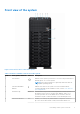
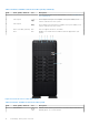
Table Of Contents
- Dell EMC PowerEdge T550 Installation and Service Manual
- Contents
- About this document
- PowerEdge T550 system overview
- Initial system setup and configuration
- Minimum to POST and system management configuration validation
- Installing and removing system components
- Safety instructions
- Before working inside your system
- After working inside your system
- Recommended tools
- Optional front bezel
- System feet
- Optional caster wheels
- System cover
- Air shroud
- Cooling fans
- Cooling fan cage
- Fan board tray
- Front PERC module
- Drives
- Removing a drive blank
- Installing a drive blank
- Removing a drive carrier
- Installing a drive carrier
- Removing the drive from the drive carrier
- Installing a drive into the drive carrier
- Removing a 3.5-inch drive adapter from a 3.5-inch drive carrier
- Installing a 3.5-inch drive adapter into the 3.5-inch drive carrier
- Removing a 2.5-inch drive from a 3.5-inch drive adapter
- Installing a 2.5-inch drive into a 3.5-inch drive adapter
- Drive backplane
- Drive bays
- Cable routing
- Optional optical drive
- Optional tape backup unit
- Front IO module
- System memory
- Optional BOSS S2 module
- M.2 BOSS card
- Optional internal USB card
- Internal USB memory key
- Optional IDSDM module
- MicroSD card
- Expansion cards
- GPU card holder
- Optional GPU card
- GPU riser
- Processor and heat sink module
- Optional OCP card
- Optional serial COM port
- System battery
- Intrusion switch module
- Power supply unit
- Power interposer board
- System board
- Trusted Platform Module
- Jumpers and connectors
- System diagnostics and indicator codes
- Getting help
- Documentation resources

Front view of the system
Figure 1. Front view of 24 x 2.5-inch drive system
Table 1. Features available on the front of the system
Item Ports, panels, and slots Icon Description
1 Power button
Indicates if the system is powered on or off. Press the power button to
manually power on or off the system.
NOTE: Press the power button to gracefully shut down an ACPI-
compliant operating system.
2 System health and ID
indicator
Indicates the status of the system. For more information about
System health and system ID indicator codes, see the www.dell.com/
poweredgemanuals.
3 Information tag
N/A The Information tag is a slide-out label panel that contains system
information such as Service Tag, NIC, MAC address, and so on. If
you have opted for the secure default access to iDRAC, then the
Information tag also contains the iDRAC secure default password.
4
Status LED indicators N/A Enables you to identify any failed hardware components. There are
up to five status LEDs and an overall system health LED bar. For
PowerEdge T550 system overview 9