Dell OptiPlex XE2 Mini Tower Owner's Manual Regulatory Model: D13M Regulatory Type: D13M001
Notes, Cautions, and Warnings NOTE: A NOTE indicates important information that helps you make better use of your computer. CAUTION: A CAUTION indicates either potential damage to hardware or loss of data and tells you how to avoid the problem. WARNING: A WARNING indicates a potential for property damage, personal injury, or death. Copyright © 2014 Dell Inc. All rights reserved. This product is protected by U.S. and international copyright and intellectual property laws.
Contents 1 Working on Your Computer....................................................................................................... 5 Before Working Inside Your Computer.....................................................................................................................5 Turning Off Your Computer....................................................................................................................................... 6 After Working Inside Your Computer....................
Removing the Power Switch...................................................................................................................................24 Installing the Power Switch....................................................................................................................................25 Removing the Input/Output (I/O) Panel...................................................................................................................
Working on Your Computer 1 Before Working Inside Your Computer Use the following safety guidelines to help protect your computer from potential damage and to help to ensure your personal safety. Unless otherwise noted, each procedure included in this document assumes that the following conditions exist: • You have read the safety information that shipped with your computer. • A component can be replaced or--if purchased separately--installed by performing the removal procedure in reverse order.
CAUTION: Before touching anything inside your computer, ground yourself by touching an unpainted metal surface, such as the metal at the back of the computer. While you work, periodically touch an unpainted metal surface to dissipate static electricity, which could harm internal components. Turning Off Your Computer CAUTION: To avoid losing data, save and close all open files and exit all open programs before you turn off your computer. 1.
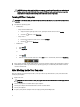
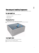
Removing and Installing Components 2 This section provides detailed information on how to remove or install the components from your computer. Recommended Tools The procedures in this document may require the following tools: • Small flat-blade screwdriver • Phillips screwdriver • Small plastic scribe Removing the Cover 1. Follow the procedures in Before Working Inside Your Computer. 2. Pull up the cover release latch, and lift the cover upwards to remove it from the computer.
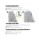
Removing the Intrusion Switch 1. Follow the procedures in Before Working Inside Your Computer. 2. Remove the cover. 3. Disconnect the intrusion-switch cable from the system board. 4. Slide the intrusion switch toward the bottom of the chassis and remove it from the computer. Installing the Intrusion Switch 1. Insert the intrusion switch into its place in the chassis rear and slide it towards the top to secure it. 2. Connect the intrusion cable to the system board. 3. Install the cover. 4.
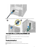
5. Press the blue tab and lift the latch outwards and remove the WLAN card from the connector on the system board. Installing the Wireless Local Area Network (WLAN) Card 1. Insert the WLAN card into the connector on the system board and press down until it is secured. 2. Affix the latch. 3. Place the antenna puck on the connector and tighten the screws to secure it to the computer. 4. Install the cover. 5. Follow the procedures in After Working Inside Your Computer. Removing the Front Bezel 1.
4. Rotate the front bezel away from the computer to release the hooks on the opposite edge of the bezel from the chassis. Installing the Front Bezel 1. Insert the hooks along the bottom edge of the front bezel into the slots on the chassis front. 2. Rotate the bezel toward the computer to engage the front-bezel retention clips until they click into place. 3. Install the cover. 4. Follow the procedures in After Working Inside Your Computer. Removing the Expansion Card 1.
NOTE: If your computer has a powered expansion card perform step 3 and step 4, else move to step 5. 3. Disconnect the power cable from the card. Press the tab to release the card-retention latch. 4. Ease the card up from its connector and remove it from the computer.
5. Rotate the release tab on the card-retention latch upward. 6. Pull the release lever away from the expansion card until you release the securing tab from the dent in the card. Then, ease the card up and out of its connector and remove it from the computer.
Installing the Expansion Card 1. Insert the expansion card into it's connector on the system board and press down until it is securely in place. NOTE: If your computer has a powered expansion connect the power cable to the card. 2. Rotate the release tab on the card-retention latch downward. 3. Install the cover. 4. Follow the procedures in After Working Inside Your Computer.
Installing the Memory 1. Align the notch on the memory-card with the tab in the system-board connector. 2. Press down on the memory module until the release tabs spring back to secure them in place. 3. Install the cover. 4. Follow the procedures in After Working Inside Your Computer. Removing the Coin-Cell Battery 1. Follow the procedures in Before Working Inside Your Computer. 2. Remove: a. cover b. expansion card(s) 3. Locate the coin-cell battery on the system board. 4.
Installing the Coin-Cell Battery 1. Place the coin cell battery in its slot on the system board and press until the release latch springs back into place and secures it. 2. Install: a. expansion card b. cover 3. Follow the procedures in After Working Inside Your Computer. Removing the Hard Drive 1. Follow the procedures in Before Working Inside Your Computer. 2. Remove: a. cover b. front bezel 3. Disconnect the data cable and the power cable from the back of the hard drive.
Installing the Hard Drive 1. Insert the hard drive into the hard-drive bracket. 2. Press the securing brackets inward and slide the hard-drive bracket into the bay. 3. Connect the data cable and the power cable to the back of the hard-drive. 4. Install the: a. front bezel b. cover 5. Follow the procedures in After Working Inside Your Computer. Removing the Optical Drive 1. Follow the procedures in Before Working Inside Your Computer. 2. Remove: a. cover b. front bezel 3.
5. Repeat steps 3 and 4 to remove the second optical drive (if available). Installing the Optical Drive 1. Push the optical drive from the front toward the back of the computer till it is secured by the optical-drive latch. 2. Connect the data cable and power cable to the back of the optical drive. 3. Install: a. front bezel b. cover 4. Follow the procedures in After Working Inside Your Computer. Removing the Speaker 1. Follow the procedures in Before Working Inside Your Computer. 2.
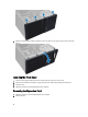
Installing the Speaker 1. Slide the speaker downwards into its slot to secure it. 2. Thread the speaker cable into the chassis clip and connect the speaker cable to the system board. 3. Install the cover. 4. Follow the procedures in After Working Inside Your Computer. Removing the Power Supply 1. Follow the procedures in Before Working Inside Your Computer. 2. Remove the cover. 3. Disconnect the 4-pin and 8-in power cables from the system board and release the cable from the tab.
4. Remove the screws that secure the power supply to the back of the computer. 5. Push in on the blue release tab beside the power supply, and slide the power supply towards the front of the computer. Lift and remove the power supply out of the computer.
Installing the Power Supply 1. Place the power supply in the chassis and slide towards the back of the system to secure it. 2. Tighten the screws to secure the power supply to the back of the computer. 3. Connect the 4-pin and 8-pin power cables to the system board. 4. Thread the power cables through the chassis clips. 5. Install the cover. 6. Follow the procedures in After Working Inside Your Computer. Removing the Heat Sink Assembly 1.
Installing the Processor 1. Insert the processor in the processor socket. Ensure the processor is properly seated. 2. Lower the processor cover. 3. Press the release lever down and then move it inward to secure it with the retention hook. 4. Install: a. heat-sink assembly b. cover 5. Follow the procedures in After Working Inside Your Computer. Removing the System Fan 1. Follow the procedures in Before Working Inside Your Computer. 2. Remove the cover. 3.
Installing the System Fan 1. Place the system fan in the chassis. 2. Pass the four grommets through the chassis and slide outward along the groove to secure in place. 3. Connect the system-fan cable to the system board. 4. Install the cover. 5. Follow the procedures in After Working Inside Your Computer. Removing the Thermal Sensor 1. Follow the procedures in Before Working Inside Your Computer. 2. Remove the cover. 3. Disconnect the thermal-sensor cable from the system board.
4. Release the thermal-sensor cable from the chassis clip. 5. Press the tabs on both sides to release and remove the thermal sensor away from the chassis.
Installing the Thermal Sensor 1. Secure the thermal sensor to the chassis. 2. Thread the thermal-sensor cable into the chassis clips. 3. Connect the thermal-sensor cable to the system board. 4. Install the cover. 5. Follow the procedures in After Working Inside Your Computer. Removing the Power Switch 1. Follow the procedures in Before Working Inside Your Computer. 2. Remove the: a. cover b. front bezel c. optical drive 3. Disconnect the power-switch cable from the system board. 4.
5. Press the clips on both side of the power switch to release it from the chassis and, slide to remove the power switch along its cable from the computer. Installing the Power Switch 1. Slide the power switch in through the front of the computer. 2. Secure the power-switch cable to the chassis. 3. Thread the power-switch cable into the chassis clips. 4. Connect the power-switch cable to the system board. 5. Install the: a. optical drive b. front bezel c. cover 6.
Removing the Input/Output (I/O) Panel 1. Follow the procedures in Before Working Inside Your Computer. 2. Remove: a. cover b. front bezel 3. Disconnect the I/O panel, data, and USB data cables from the system board. 4. Unthread and release the I/O Panel, data cable and USB data cable from the clip on the computer. 5. Remove the screw that secures the I/O panel to the computer. 6.
Installing the Input/Output (I/O) Panel 1. Insert the I/O panel into the slot on the chassis front. 2. Slide the I/O panel towards the right of the computer to secure to the chassis. 3. Tighten the screw to secure the I/O panel to the chassis. 4. Thread the I/O panel, data cable and USB data cable into the chassis clip. 5. Connect the I/O panel, data cable and USB data cable to the system board. 6. Install : a. front bezel b. cover 7. Follow the procedures in After Working Inside Your Computer.
5. Tilt the system board at 45–degrees, and then lift the system board out of the computer. Installing the System Board 1. Align the system board to the port connectors on the rear of the chassis and place the system board in the chassis. 2. Tighten the screws securing the system board to the chassis. 3. Connect the cables to the system board. 4. Install the: a. b. c. d. e. 5.
System Board Components Figure 1. Components Of The System Board 1. PCI Express x16 slot (wired as x4) 2. PCI slot 3. PCIe x1 slot 4. coin-cell battery 5. PCI Express x16 slot 6. intrusion switch connector 7. 4-pin CPU power connecter 8. system fan connector 9. CPU Socket 10. heat-sink fan connector 11. DDR DIMM memory slots (4) 12. front power-switch connector 13. 8-pin power connector 14. SATA connectors 15. HDD and optical drive power connector 16. SATA connectors 17.
System Setup 3 System Setup enables you to manage your computer hardware and specify BIOS‐level options.
Table 1. Navigation Keys Keys Navigation Up arrow Moves to the previous field. Down arrow Moves to the next field. Allows you to select a value in the selected field (if applicable) or follow the link in the field. Spacebar Expands or collapses a drop‐down list, if applicable. Moves to the next focus area. NOTE: For the standard graphics browser only. Moves to the previous page till you view the main screen.
Table 3. System Configuration Option Description Integrated NIC Allows you to enable or disable the integrated network card. You can set the integrated NIC to: • • • • Disabled Enabled Enabled w/PXE Enabled w/Cloud Desktop NOTE: Depending on the computer and its installed devices, the items listed in this section may or may not appear. Serial Port Allows you to define the serial port settings.
Option Description If USB port is enabled, device attached to this port is enabled and available for operation system. If USB port is disabled, the operation system cannot see any device attached to this port.
Option Description NOTE: The system will always prompt for the system and internal HDD passwords when powered on from the off state (a cold boot). Also, the system will always prompt for passwords on any module bay HDDs that may be present. Password Change Allows you to determine whether changes to the system and hard disk passwords are permitted when an administrator password is set. • TPM Security Allow Non-Admin Password Changes - This option is enabled by default.
NOTE: For enable system need to be UEFI boot mode and enable legacy option ROMs to be turned off. Expert key Management Allows you to manipulate the security key databases only if the system is in Custom Mode. The Enable Custom Mode option is disabled by default. The options are: • • • • PK KEK db dbx If you enable the Custom Mode, the relevant options for PK, KEK, db, and dbx appear.
Option Description Hyper-Thread Control Allows you to enable or disable the Hyper-Threading technology. This option is enabled by default. Rapid Start Technology Allows you to improve batter life by automatically putting the system into a low power status during after user specified amount of time.
Option Description • Wake on LAN Enable USB Wake Support - This option is disabled by default. This option allows the computer to power up from the off state when triggered by a special LAN signal. Wake-up from the Standby state is unaffected by this setting and must be enabled in the operating system. This feature only works when the computer is connected to AC power supply. The options differ based on the form factor.
Option Description • VT for Direct I/O Enables or disables the Virtual Machine Monitor (VMM) from utilizing the additional hardware capabilities provided by Intel® Virtualization technology for direct I/O. • Trusted Execution Enable Intel Virtualization Technology - This option is enabled by default. Enable Intel Virtualization Technology for Direct I/O - This option is enabled by default.
Option Description • • Static IP DHCP (enabled by default) NOTE: This field is only relevant when the Integrated NIC control in the System Configuration group is set to Enabled with ImageServer. Client IP Address Specifies the static IP address of the client. The default IP address is 255.255.255.255. NOTE: This field is only relevant when the Integrated NIC control in the System Configuration group is set to Enabled with ImageServer and when Client DHCP is set to Static IP.
7. Click Get drivers and click View All Drivers. The Drivers and Downloads page opens. 8. On the Drivers and Downloads screen, under the Operating System drop-down list, select BIOS. 9. Identify the latest BIOS file and click Download File. You can also analyze which drivers need an update. To do this for your product, click Analyze System for Updates and follow the instructions on the screen. 10.
To enter a system setup, press immediately after a power-on or re-boot. 1. In the System BIOS or System Setup screen, select System Security and press . The System Security screen appears. 2. In the System Security screen, verify that Password Status is Unlocked. 3. Select System Password , enter your system password, and press or . Use the following guidelines to assign the system password: • A password can have up to 32 characters.
3. Identify the PSWD jumper on the system board. 4. Remove the PSWD jumper from the system board. NOTE: The existing passwords are not disabled (erased) until the computer boots without the jumper. 5. Install the cover. NOTE: If you assign a new system and/or setup password with the PSWD jumper installed, the system disables the new password(s) the next time it boots. 6. Connect the computer to the electrical outlet and power-on the computer. 7.
Diagnostics 4 If you experience a problem with your computer, run the ePSA diagnostics before contacting Dell for technical assistance. The purpose of running diagnostics is to test your computer's hardware without requiring additional equipment or risking data loss. If you are unable to fix the problem yourself, service and support personnel can use the diagnostics results to help you solve the problem.
Troubleshooting Your Computer 5 You can troubleshoot your computer using indicators like Diagnostic Lights, Beep Codes, and Error Messages during the operation of the computer. Power LED Diagnostics The power button LED located on the front of the chassis also functions as a bicolored diagnostic LED. The diagnostic LED is only active and visible during the POST process. Once the operating system starts to load, it is no longer visible.
Amber LED State Description 3,7 some other failure with messages on screen Beep Code The computer can emit a series of beeps during start-up if the display does not show errors or problems. These series of beeps, called beep codes, identify various problems. The delay between each beep is 300 ms, the delay between each set of beeps is 3 sec, and the beep sound lasts 300 ms. After each beep and each set of beeps, the BIOS should detect if the user presses the power button.
Error Message Description Decreasing available memory One or more memory modules may be faulty or improperly seated. Re-install the memory modules and, if necessary, replace them. Diskette drive 0 seek failure A cable may be loose or the computer configuration information may not match the hardware configuration. Diskette read failure The floppy disk may be defective or a cable may be loose. If the drive access light turns on, try a different disk.
Error Message Description Memory double word A memory module may be faulty or improperly seated. Reinstall the memory modules and, if logic failure at necessary, replace them. address, read value expecting value Memory odd/even logic failure at address, read value expecting value A memory module may be faulty or improperly seated.
Error Message Description Time-of-day not setplease run the System Setup program The time or date stored in System Setup does not match the computer clock. Timer chip counter 2 failed A chip on the system board may be malfunctioning. Unexpected interrupt The keyboard controller may be malfunctioning or a memory module may be loose.
6 Specifications NOTE: Offerings may vary by region. For more information regarding the configuration of your computer, click Start (Start icon) → Help and Support, and then select the option to view information about your computer. Table 15. Processor Feature Processor type Total cache Specification • • • • Intel Core i3 series Intel Core i5 series Intel Core i7 series Intel Pentium Dual Core series Up to 8 MB cache depending on processor type Table 16.
Table 19. Network Feature Specification Integrated Intel 1217LM Ethernet capable of 10/100/1000 Mb/s communication Table 20. System Information Feature Specification System chipset Intel 8 Series Express chipset DMA channels two 8237 DMA controllers with seven independently programmable channels Interrupt levels Integrated I/O APIC capability with 24 interrupts BIOS chip (NVRAM) 12 MB Table 21. Expansion Bus Feature Specification Bus type PCIe gen2, gen3 (x16), USB 2.0, and USB 3.
Feature Small Form Factor Internally Accessible: Specification one slim optical drive bay 3.5-inch SATA drive bays 2.5-inch SATA drive bays Mini Tower two two Small Form Factor one two Table 24.
Feature Specification Off (no light) — The computer is not detecting a physical connection to the network. Network activity light on integrated network adapter Yellow light — A blinking yellow light indicates that network activity is present. Power supply diagnostic light Green light — The power supply is turned on and is functional. The power cable must be connected to the power connector (at the back of the computer) and the electrical outlet. Table 26.
Feature Non-Operating Specification 1.37 GRMS Maximum shock: Operating 40 G Non-Operating 105 G Altitude: Operating –15.2 m to 3048 m (–50 to 10,000 ft) Non-Operating –15.20 m to 10,668 m (–50 ft to 35,000 ft) Airborne contaminant level G1 or lower as defined by ANSI/ISA-S71.
Contacting Dell To contact Dell for sales, technical support, or customer service issues: 1. Visit support.dell.com. 2. Verify your country or region in the Choose a Country/Region drop-down menu at the bottom of the page. 3. Click Contact Us on the left side of the page. 4. Select the appropriate service or support link based on your need. 5. Choose the method of contacting Dell that is convenient for you.