
Service Manual

USB Board 125
3
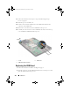
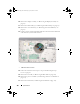
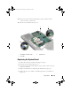
Replace the screw that secures the USB board to the top cover.
4
Slide the USB-board cable into the connector on the USB board and press
the connector latch down to secure the cable.
5
Follow the instructions from step 11 to step 15 in "Replacing the Top
Cover" on page 87.
6
Replace the Mini-Card(s) (see "Replacing the Mini-Card(s)" on page 23).
7
Replace the display assembly (see "Replacing the Display Assembly" on
page 58).
8
Replace the keyboard (see "Replacing the Keyboard" on page 45).
9
Replace the palm-rest assembly (see "Replacing the Palm-Rest Assembly"
on page 40).
10
Replace the optical drive (see "Replacing the Optical Drive" on page 34).
11
Follow the instructions in step 5 in "Replacing the Hard Drive(s)" on
page 30.
12
Replace the memory module(s) (see "Replacing the Memory Module(s)"
on page 18).
13
Replace the module cover (see "Replacing the Module Cover" on page 16).
14
Replace the battery (see "Replacing the Battery" on page 14).
CAUTION: Before turning on the computer, replace all screws and ensure that no
stray screws remain inside the computer. Failure to do so may result in damage to
the computer.
book.book Page 125 Wednesday, April 25, 2012 2:11 PM