
Service Manual

64 Display
2
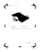
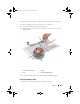
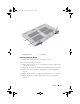
Place the display panel over the display back cover.
3
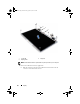
Route the display cable through the routing guide on the left display
hinge.
4
Route the antenna cables through the routing guide on the right display
hinge.
5
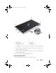
Replace the touch-screen board, if applicable:
a
Connect the touch-screen board cable to the connector on the touch-
screen board.
b
Replace the eight screws that secure the display panel to the display
back cover.
6
Replace the IR emitter board, if applicable:
a
Connect the IR emitter board cable to the connector on the IR
emitter board.
b
Replace the six screws that secure the display panel to the display back
cover.
7
Replace the camera module (see "Replacing the Camera Module" on
page 80).
8
Replace the display bezel (see "Replacing the Display Bezel" on page 60).
9
Replace the display assembly (see "Replacing the Display Assembly" on
page 58).
CAUTION: Before turning on the computer, replace all screws and ensure that no
stray screws remain inside the computer. Failure to do so may result in damage to
the computer.
Display Cable
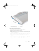
Removing the Display Cable
1
Follow the instructions in "Before You Begin" on page 9.
2
Remove the display assembly (see "Removing the Display Assembly" on
page 55).
3
Remove the display bezel (see "Removing the Display Bezel" on page 59).
4
Remove the camera module ("Removing the Camera Module" on
page 77).
book.book Page 64 Wednesday, April 25, 2012 2:11 PM