Dell™ XPS™ 210 Service Manual Before You Begin About Your Computer Technical Overview Specifications Troubleshooting System Setup Removing the Computer Cover Removing and Installing Parts Replacing the Computer Cover Notes, Notices, and Cautions NOTE: A NOTE indicates important information that helps you make better use of your computer. NOTICE: A NOTICE indicates either potential damage to hardware or loss of data and tells you how to avoid the problem.
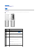
Back to Contents Page About Your Computer Dell™ XPS™ 210 Service Manual Front View Back View Front View NOTE: The front panel door does not close when you are using certain Flash Media, IEEE 1394, USB, or headphone connectors. -1 CD/DVD drive eject button Press this button to eject a CD/DVD from the drive. 2 CD/DVD drive activity light The drive activity light is on when the computer reads data from the CD or DVD drive. 3 USB 2.
NOTICE: To avoid losing data, do not use the power button to turn off the computer. Instead, perform an operating system shutdown. 7 power light The power light illuminates and indicates different power states: ¡ ¡ ¡ ¡ No light — The computer is turned off. Steady green — The computer is in a normal operating state. Blinking green — The computer is in a power-saving state. Blinking or solid amber — See Power Problems in your computer Owner's Manual.
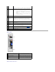
1 link integrity light l l l 2 network adapter connector Green — A good connection exists between a 10-Mbps network and the computer. Orange — A good connection exists between a 100-Mbps network and the computer. Off — The computer is not detecting a physical connection to the network. To attach your computer to a network or broadband device, connect one end of a network cable to either a network jack or your network or broadband device.
Back to Contents Page Before You Begin Dell™ XPS™ 210 Service Manual Getting Started Recommended Tools Turning Off Your Computer Before Working Inside Your Computer Getting Started This manual provides procedures for removing and replacing the components in your computer. Unless otherwise noted, each procedure assumes that the following conditions exist: l You have performed the steps in Turning Off Your Computer and Before Working Inside Your Computer.
NOTICE: To disconnect a network cable, first unplug the cable from your computer and then unplug it from the network port or device. 2. Disconnect any telephone or network cables from the computer. 3. Disconnect your computer and all attached devices from their electrical outlets, and then press the power button to ground the system board. CAUTION: To guard against electrical shock, always unplug your computer from the electrical outlet before opening the cover. 4.
Back to Contents Page Replacing the Computer Cover Dell™ XPS™ 210 Service Manual CAUTION: Before you begin any of the procedures in this section, follow the safety instructions in the Product Information Guide. 1. Ensure that all cables are connected and folded out of the way. Gently pull the power cables toward you so that they do not get caught underneath the drives. 2. Ensure that no tools or extra parts are left inside the computer. 3. Install the cover: a.
Back to Contents Page Removing the Computer Cover Dell™ XPS™ 210 Service Manual CAUTION: Before you begin any of the procedures in this section, follow the safety instructions in the Product Information Guide. CAUTION: To guard against electrical shock, always unplug your computer from the electrical outlet before opening the cover. NOTICE: Before touching anything inside your computer, ground yourself by touching an unpainted metal surface, such as the metal at the back of the computer.
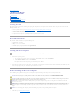
Back to Contents Page Removing and Installing Parts Dell™ XPS™ 210 Service Manual Memory Processor Cards Modem Hard Drive Power Supply CD/DVD Drive System Board Floppy Drive (Optional) Front I/O Panel Media Card Reader (Optional) Battery Heat Sink Assembly Front Panel Fan Assembly Memory You can increase your computer memory by installing memory modules on the system board. Your computer supports unbuffered, non-ECC, DDR2 memory. NOTE: Buffered memory is not supported on this computer.
2 matched pair of memory modules in DIMM connectors 3 and 4 (black securing clips) NOTICE: If you remove your original memory modules from the computer during a memory upgrade, keep them separate from any new modules that you may have, even if you purchased the new modules from Dell. If possible, do not pair an original memory module with a new memory module. Otherwise, your computer may not start properly.
5. Replace the computer cover (see Replacing the Computer Cover). NOTICE: To connect a network cable, first plug the cable into the network port or device and then plug it into the computer. 6. Connect your computer and devices to electrical outlets, and then turn them on. 7. When a message appears stating that memory size has changed, press to continue. 8. Log on to your computer. 9. Right-click the My Computer icon, then click Properties. 10. Click the General tab. 11.
1 PCI Express x16 card 4 PCI Express x16 card slot 2 PCI Express x1 card 3 PCI Express x1 card slot If you are installing or replacing a PCI Express card, follow the procedures in the next section. If you are removing but not replacing a card, see Removing a PCI Express Card. If you are replacing a card, remove the current driver for the card from the operating system. Installing a PCI Express Card 1. Follow the procedures in Before You Begin. 2.
7. Place the card in the connector and press down firmly. Ensure that the card is fully seated in the slot. 1 card not fully seated 4 card fully seated 8. 9. 2 bracket within slot 3 bracket caught outside of slot Before you close the card retention door, ensure that: l The tops of all cards and filler brackets are flush with the alignment bar. l The notch in the top of the card or filler bracket fits around the alignment guide.
Removing a PCI Express Card 1. Follow the procedures in Before You Begin. 2. Gently push the release tab on the card retention door from the inside to pivot the door open. Because the door is attached, it will remain in the open position. 3. Gently pull back the securing tab, grasp the card by its top corners, and then ease it out of its connector. If necessary, disconnect any cables connected to the card. 4.
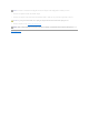
NOTICE: Do not pull the drive out of the computer by the drive cables. Doing so may cause damage to the cables and cable connectors. 3. 1 Lift the drive out of the computer and disconnect the power and hard-drive cables from the drive. power cable 2 hard drive cable or serial ATA data cable Installing a Hard Drive 1. Follow the procedures in Before You Begin. 2. Remove the old hard drive, as needed (see Removing a Hard Drive). 3. Unpack the hard drive, and prepare it for installation. 4.
1 power cable 2 hard drive plastic latch 3 hard drive cable or serial ATA data cable 4 open bay 6. Check all connectors to be certain that they are properly cabled and firmly seated. 7. Gently slide the drive into the open bay until the hard drive plastic latch attaches to the hard drive holder on the chassis. 1 tabs (2) 4 hard drive plastic latch 2 hard drive 3 hard drive holder on the chassis 8. Align the drive screw holes with the screws projecting upwards on the heat sink holder. 9.
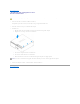
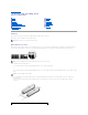
1. Follow the procedures in Before You Begin. NOTICE: Do not pull the drive out of the computer by the drive cables. Doing so may cause damage to the cables and cable connectors. 2. Pull up on the drive release latch and slide the drive towards the back of the computer. 3. Carefully, lift the drive away from the computer. 1 drive release latch 2 CD/DVD drive 4. Disconnect the data cable from the CD/DVD connector on the system board (see System Board Components). 5.
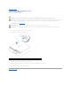
1 data cable 2 power cable 3 CD/DVD connector 4. Connect the data cable to the CD/DVD connector on the system board. 5. Gently position the drive until it clicks into place. 1 CD/DVD drive 2 CD/DVD drive bracket 6. Check all cable connections, and fold cables out of the way to provide airflow for the fan and cooling vents. 7. Replace the computer cover (see Replacing the Computer Cover). 8. Connect your computer and devices to electrical outlets, and then turn them on. 9.
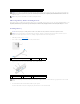
4. 1 Carefully, lift the drive away from the computer. drive release latch 5. 2 floppy drive Disconnect the floppy drive interface cable from the system board (see System Board Components). NOTE: The interface cable is held in place by the metal drive bracket and does not need to be removed from the drive.
4. 1 Attach the interface cable to the system board (see System Board Components). cable release tab 2 interface cable edge connector 3 interface cable 5. Check all cable connections, and fold cables out of the way to avoid blocking the fan and cooling vents. 6. Replace the CD/DVD drive (see Installing a CD/DVD Drive). 7. Replace the computer cover (see Replacing the Computer Cover).
1. Follow the procedures in Before You Begin. 2. Remove the CD/DVD drive, if installed (see Removing a CD/DVD Drive). 3. Remove the hard drive (see Removing a Hard Drive). 4. Disconnect the interface cable from the back of the Media Card Reader and from the Media Card Reader connector on the system board (see System Board Components). 1 interface cable 5.
1 drive 2 drive bracket 3 screws (4) 3. Slide the drive into place until you feel a click or feel the drive securely installed. 4. Connect the interface cable to the back of the Media Card Reader and to the Media Card Reader connector on the system board (see System Board Components). 1 interface cable 5. Replace the hard drive (see Installing a Hard Drive). 6. Replace the CD/DVD drive (see Installing a CD/DVD Drive). 7. Replace the computer cover (see Replacing the Computer Cover).
1. Follow the procedures in Before You Begin. 2. Remove the CD/DVD drive, if installed (see Removing a CD/DVD Drive). 1 heat sink assembly CAUTION: The heat sink assembly can get very hot during normal operation. Be sure that the assembly has had sufficient time to cool before you touch it. 3. Remove the two screws from either side of the heat sink assembly. NOTICE: After you remove the heat sink assembly, lay the assembly on its side.
4. Disconnect the fan power cable from the CPUFAN connector on the system board (see System Board Components). 1 fan assembly 4 fan tabs (2) 2 fan cable connector 3 fan release lever 5. Press the fan release lever, then slide the fan towards the back of the computer to release the two fan tabs from the keyhole slots in the chassis. 6. Carefully, remove the fan from the computer. Installing the Fan Assembly When reinstalling the fan, ensure that you do not pinch any wires that run near the fan.
1 processor cover 4 release lever 5. 2 processor 3 processor socket Open the processor cover, and then carefully remove the processor from the socket. Leave the release lever extended in the release position so that the socket is ready for the new processor. Installing the Processor NOTICE: To prevent static damage to components inside your computer, discharge static electricity from your body before you touch any of your computer's electronic components.
NOTICE: Socket pins are delicate. To avoid damage, ensure that the processor is aligned properly with the socket, and do not use excessive force when you install the processor. 5. Gently place the processor in the socket and check to ensure that the processor is positioned correctly. 6. When the processor is fully seated in the socket, close the processor cover. Ensure that the securing tab on the processor cover is positioned underneath the center cover latch on the socket. 7.
1 pull tab 2 modem cable 3 screws (2) 4 RJ11 internal connector (RJ11INT) 5 modem 6 T-shaped connector attached to the modem cable 4. Install the new modem: a. Connect the T-shaped connector of the modem cable to the modem. b. Align the modem with the screw holes and press the modem into its connector on the system board (see System Board Components). NOTICE: The connectors are keyed to ensure correct insertion. If you feel resistance, check the connectors for proper orientation, then try again.
1 power supply screws (3) 5. Slide the power supply approximately 1 inch toward the front of the computer. 6. Carefully lift the power supply out of the computer. Replacing the Power Supply 1. Lower the power supply into the computer and slide the power supply toward the back of the computer. 2. Replace the three power supply screws. 3. Reconnect all DC power cables. 4. Replace the computer cover (see Replacing the Computer Cover). 5. Connect the AC power cable to the power supply connector.
5. Before you remove the existing system board, visually compare the replacement system board to the existing board to ensure that you have the correct part. 6. Remove the six screws that secure the system board to the bottom of the computer. 7. Slide the system board assembly toward the front of the computer, and then carefully lift the system board up and out of the computer. 1 screws (6) 8.
Front I/O Panel CAUTION: Before you begin any of the procedures in this section, follow the safety instructions in the Product Information Guide. CAUTION: To guard against electrical shock, always unplug your computer from the electrical outlet before opening the cover. Removing the Front I/O Panel 1. Follow the procedures in Before You Begin. 2. Remove the heat sink (see Removing the Heat Sink Assembly). 3. Remove the fan assembly (see Removing the Fan Assembly). 4.
2. Press the case so that the tabs fix firmly into the slots in the chassis. 3. Press the LED card case release lever and slide the case towards the top of the chassis until you hear a click and the case locks in position. 4. Replace the cable connected to the card. Battery CAUTION: Before you begin any of the procedures in this section, follow the safety instructions in the Product Information Guide.
Front Panel 1. Follow the procedures in Before You Begin. 2. Remove the CD/DVD drive (see Removing a CD/DVD Drive). 3. Remove the optional Media Card Reader (see Removing a Media Card Reader). 4. Remove the optional floppy drive (see Removing a Floppy Drive). 5. Use a screwdriver to press in against the locking tab that secures the computer base until it releases the surrounding metal. 6. Slide the base towards the rear of the computer, then pull it towards you to remove it.
1 release tabs 2 top 13. Lift up on the front panel to release the top two tabs that attach it to the computer chassis. 14. Pull up on the lower tab to release it from the computer chassis and lift the front panel from the computer.
Back to Contents Page Specifications Dell™ XPS™ 210 Service Manual Processor Processor types Intel® Pentium® 4, Pentium® D, Celeron® D, Intel Core™ processor Level 2 (L2) cache 1 MB for Pentium 4 5XX processors (with Hyper Threading) 2 MB for Pentium 4 6XX processors (with Hyper Threading) 2 x 2 MB for Pentium D 9XX processors (with dual core) 2 x 1 MB for Pentium D 8XX processors (with dual core) 256K for Celeron D 3XX processors 2 MB for Intel Core E6400 processors and earlier 4 MB for Intel Core E66
x1 slot bidirectional speed: 500 MB/sec x16 slot bidirectional speed: 8 GB/sec PCI Express: connector one x1 connector size 36 pins connector data width (maximum) one PCI Express lane PCI Express: connector one x16 connector size 164 pins connector data width (maximum) 16 PCI Express lanes Drives Externally accessible one slimline 3.5-inch media bay one slimline 5.
Controls and Lights Power control push button Power light green light — Blinking green in sleep state; solid green for power-on state. amber light — Blinking amber indicates a problem with an installed device; solid amber indicates an internal power problem (see "Power Problems" in your computer Owner's Manual). Hard drive access light green Link integrity light (on integrated network adapter) green light — A good connection exists between a 10-Mbps network and the computer.
Back to Contents Page System Setup Dell™ XPS™ 210 Service Manual Overview Entering System Setup System Setup Options Boot Sequence Clearing Forgotten Passwords Clearing CMOS Settings Flashing the BIOS Overview Use system setup as follows: l To change the system configuration information after you add, change, or remove any hardware in your computer l To set or change a user-selectable option such as the user password l To read the current amount of memory or set the type of hard drive installed Befo
System Setup Options NOTE: Depending on your computer, BIOS version, and installed devices, the items listed in this section may not appear, or may not appear exactly as listed. System System Info Lists system information such as the computer name, the BIOS version number and date, system tags, and other system-specific information. NOTE: The system name listed in the BIOS may not appear exactly as the name that appears on the computer or in the computer's documentation.
Video Specifies which video controller is primary when two video controllers are present on the computer. Auto enables the add-in video controller. Onboard enables the integrated video controller. Primary Video (Auto default) Configures the system memory allocation reserved for the integrated video controller. Settings are 1MB and 8MB. Video Memory Size (8 MB default) Performance Determines whether the physical processor appears as one or two logical processors.
Quick Resume Enables or disables the Intel® Quick Resume Technology mode for providing rapid response to power button presses. Maintenance Controls the SERR DMI message mechanism. SERR DMI Message (On default) NOTE: Some graphics cards require that the SERR DMI message mechanism be disabled. Load Defaults Restores System Setup options to their factory defaults. Event Log Allows you to view the Event Log. Entries are marked R for Read and U for Unread.
You can use this feature, for example, to restart your computer to a USB device such as a floppy drive, memory key, or CD-RW drive. NOTE: If you are booting to a USB floppy drive, you must first set the floppy drive to OFF in system setup (see System Setup Options). 1. If you are booting to a USB device, connect the USB device to a USB connector (see About Your Computer). 2. Turn on (or restart) your computer. 3. When the DELL logo appears, press immediately.
NOTICE: To connect a network cable, first plug the cable into the network wall jack and then plug it into the computer. 11. Connect your computer and devices to electrical outlets, and then turn them on. NOTE: In system setup (see System Setup), both system and administrator password options appear as Not Set. The password feature is enabled but a password is not assigned. 12. Assign a new system and/or administrator password, as needed.
Back to Contents Page Technical Overview Dell™ XPS™ 210 Service Manual Inside View of Your Computer System Board Components Power Supply DC Connector Pin Assignments Inside View of Your Computer CAUTION: Before you begin any of the procedures in this section, follow the safety instructions in the Product Information Guide. CAUTION: To guard against electrical shock, always unplug your computer from the electrical outlet before opening the cover.
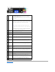
1 processor fan connector (CPUFAN) 16 modem connector (RJ11) 2 processor connector (CPU) 17 RJ11 internal connector (RJ11INT) 3 processor power connector (POWER12V) 18 video connector (VGA) 4 memory module connectors (2, 4) 19 Media Card Reader connector (USBINT) 5 memory module connectors (1, 3) 20 USB connectors (4) (USB_BACK) 6 battery socket (BATTERY) 21 network connector (NIC) and USB connectors (2) (NIC_USB1) 7 internal speaker (SPKR) 22 back panel IEEE 1394 connector (BACK1394) 8
Jumper Setting Description CLRPSWD Password features are enabled (default setting). Password features are disabled. CLRCMOS The real-time clock has not been reset. The real-time clock is being reset (jumpered temporarily).
Pin Number Signal Name 18-AWG Wire 1 +3.3 VDC Orange 2 +3.3 VDC Orange 3 COM Black 4 +5 VDC Red 5 COM Black 6 +5 VDC Red 7 COM Black 8 POK* Gray 9 +5 VFP Purple 10 +12 VDC Yellow 11 +12 VDC* Yellow 12 +3.3 VDC Orange 13 +3.3 VDC/SE Orange 14 -12 VDC Blue 15 COM Black 16 PS_ON* Green 17 COM Black 18 COM Black 19 COM Black 20 N.C. N.C. 21 +5 VDC Red 22 +5 VDC Red 23 +5 VDC Red 24 COM Black *Uses 22 AWG wire instead of 18 AWG.
DC Power Connector P5 Pin Number Signal Name 18-AWG Wire 1 COM Black 2 +5 VDC Red 3 KEY N/A 4 +3.
Back to Contents Page Troubleshooting Dell™ XPS™ 210 Service Manual Dell Diagnostics System Lights Diagnostic Lights Beep Codes Dell Diagnostics CAUTION: Before you begin any of the procedures in this section, follow the safety instructions located in the Product Information Guide. When to Use the Dell Diagnostics If you experience a problem with your computer, perform the checks in this section and run the Dell Diagnostics before you contact Dell for technical assistance.
For any problem encountered during a test, a message appears with an error code and a description of the problem. Write down the error code and problem description exactly as it appears and follow the instructions on the screen. If you cannot resolve the problem, see "Contacting Dell" in your Owner's Manual for instructions on obtaining technical assistance. NOTE: The Service Tag for your computer is located at the top of each test screen. When contacting Dell support, have your Service Tag ready.
To help you troubleshoot a problem, your computer has four lights labeled 1, 2, 3, and 4 on the front panel (see Front View). When the computer starts normally, the lights flash before turning off. If the computer malfunctions, the sequence of the lights identify the problem. NOTE: After the computer completes POST, all four lights turn off before booting to the operating system. Light Pattern Problem Description The computer is in a normal off condition or a possible pre-BIOS failure has occurred.
1-2-1 Programmable interval timer failure 1-2-2 DMA initialization failure 1-2-3 DMA page register read/write failure 1-3 Video Memory Test failure 1-3-1 through 2-4-4 Memory not being properly identified or used 3-1-1 Slave DMA register failure 3-1-2 Master DMA register failure 3-1-3 Master interrupt mask register failure 3-1-4 Slave interrupt mask register failure 3-2-2 Interrupt vector loading failure 3-2-4 Keyboard Controller Test failure 3-3-1 NVRAM power loss 3-3-2 Invalid NVRAM