Dell™ XPS™ 625 Service Manual Technical Overview Before You Begin Replacing the Computer Cover Replacing Memory Module(s) Replacing PCI/PCI Express Cards Replacing Drives Replacing Fans Replacing the Processor Heat Sink Replacing the Processor Replacing the System Board Replacing the Power Supply Replacing the Front I/O Panel Replacing the Master I/O Board Replacing Lights Replacing the Battery System Setup Model DCDR01 Notes, Cautions, and Warnings NOTE: A NOTE indicates important information that helps
Back to Contents Page Before You Begin Dell™ XPS™ 625 Service Manual Technical Specifications Recommended Tools Turning Off Your Computer Safety Instructions This chapter provides procedures for removing and installing the components in your computer. Unless otherwise noted, each procedure assumes that the following conditions exist: l You have performed the steps in Turning Off Your Computer and Safety Instructions. l You have read the safety information that ships with your computer.
. Disconnect all telephone or network cables from the computer. 4. Disconnect your computer and all attached devices from their electrical outlets. 5. Press and hold the power button while the system is unplugged to ground the system board. CAUTION: Before touching anything inside your computer, ground yourself by touching an unpainted metal surface, such as the metal at the back of the computer.
Back to Contents Page Replacing PCI/PCI Express Cards Dell™ XPS™ 625 Service Manual Removing PCI and PCI Express Cards Installing PCI and PCI Express Cards Removing a PCI Express Graphics Card From a Dual Configuration Installing a PCI Express Graphics Card in a Dual Configuration Configuring Your Computer After Removing or Installing a PCI/PCI Express Card WARNING: Before working inside your computer, read the safety information that shipped with your computer.
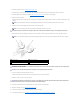
1 release tab 2 card retainer 3 screw 4 alignment guide 5 fan cage 6 alignment guide release tab 6. Press the securing tab (if present) on the system board connector as you grasp the card by its top corners, and then ease the card out of the connector. 1 PCI Express x16 card 2 securing tab 3 PCI Express x16 card slot 7. Install a filler bracket in the empty card-slot opening. If you are replacing the card, see Installing PCI and PCI Express Cards.
2. Remove the computer cover (see Replacing the Computer Cover). 3. Press down the tab on the top of the card retainer at the appropriate card slot and pivot the card retainer back through the chassis wall. 4. Remove the filler bracket or existing card (see Removing PCI and PCI Express Cards) to create a card-slot opening. 5. Prepare the card for installation.
Removing a PCI Express Graphics Card From a Dual Configuration NOTE: Follow the steps described in this section to remove PCI Express x16 graphics cards in dual configuration only. For removal of any other type of PCI or PCI Express cards, see Removing PCI and PCI Express Cards. 1. Follow the procedures in Before You Begin. 2. Remove the computer cover (see Replacing the Computer Cover). 3.
This section pertains to dual PCI Express graphics card configurations only. For installation of other types of PCI or PCI Express cards, see Installing PCI and PCI Express Cards. The PCI Express x1 card slot is not available for use if a graphics card is installed in each of the PCI Express x16 card slots in a dual-graphics card configuration.
NOTE: For information on location of connectors, see the Setup Guide. For information on installing drivers and software for your card, see the documentation that shipped with the card. Installed Sound Card 1. 2. 3. Network Card 1. 2. 3. Removed Enter system setup (see Entering System Setup) Go to Integrated Audio Controller and then change the setting to Off. Connect the external audio devices to the sound card's connectors. 1.
Back to Contents Page Replacing the Battery Dell™ XPS™ 625 Service Manual WARNING: Before working inside your computer, read the safety information that shipped with your computer. For additional safety best practices information, see the Regulatory Compliance Homepage at www.dell.com/regulatory_compliance. WARNING: A new battery can explode if it is incorrectly installed. Replace the battery only with the same or equivalent type recommended by the manufacturer.
Back to Contents Page Replacing the Computer Cover Dell™ XPS™ 625 Service Manual WARNING: Before working inside your computer, read the safety information that shipped with your computer. For additional safety best practices information, see the Regulatory Compliance Homepage at www.dell.com/regulatory_compliance. WARNING: To guard against electrical shock, always unplug your computer from the electrical outlet before removing the cover.
1 computer cover 2 cover hinge tabs (2) 3 hinge slots 7. With the help of an assistant, carefully set the computer upright. 8. Connect your computer and devices to electrical outlets, and turn them on.
Back to Contents Page Replacing the Processor Dell™ XPS™ 625 Service Manual WARNING: Before working inside your computer, read the safety information that shipped with your computer. For additional safety best practices information, see the Regulatory Compliance Homepage at www.dell.com/regulatory_compliance. CAUTION: Do not perform the following steps unless you are familiar with hardware removal and replacement. Performing these steps incorrectly could damage your system board.
CAUTION: Socket pins are delicate. To avoid damage, ensure that the processor is aligned properly with the socket, and do not use excessive force when you install the processor. Be careful not to touch or bend the pins on the system board. 8. Set the processor lightly in the socket and ensure that the processor is aligned in the socket. When the processor is positioned correctly, apply minimal pressure to seat it. 9.
Back to Contents Page Replacing the Processor Heat Sink Dell™ XPS™ 625 Service Manual WARNING: Before working inside your computer, read the safety information that shipped with your computer. For additional safety best practices information, see the Regulatory Compliance Homepage at www.dell.com/regulatory_compliance. CAUTION: Do not perform the following steps unless you are familiar with hardware removal and replacement. Performing these steps incorrectly could damage your system board.
Back to Contents Page Replacing Drives Dell™ XPS™ 625 Service Manual Replacing a Hard Drive Replacing the Drive Panel Replacing a Media Card Reader Replacing an Optical Drive WARNING: Before working inside your computer, read the safety information that shipped with your computer. For additional safety best practices information, see the Regulatory Compliance Homepage at www.dell.com/regulatory_compliance.
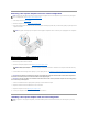
1 black tabs (2) 2 hard drive 3 hard-drive bay 5. To replace or install a new hard drive, prepare the new hard drive for installation and check the documentation for the hard drive to verify that the hard drive is configured for your computer. NOTE: If the hard drive you are installing does not have a hard-drive bracket attached, use your original hard-drive bracket; snap the bracket onto the new drive. 1 hard drive 2 hard-drive bracket 6. Verify that the hard-drive bay is empty and unobstructed. 7.
1. Follow the procedures in Before You Begin. 2. Remove the computer cover (see Replacing the Computer Cover). 3. Grasp the drive-release latch and slide it towards the base of the computer until the drive panel snaps open. 1 drive-release latch 2 drive panel 3 drive-panel tabs (3) 4. Pivot the drive panel outward and lift it from its side hinges. 5. Set the drive panel aside in a secure location. 6. To replace the drive panel, align the drive-panel tabs with the side-door hinges.
1 media card reader cable 5. Slide the drive-release latch towards the base of the computer to release the shoulder screw, and then slide the media card reader out of the drive bay. 1 drive-release latch 2 media card reader 6. If no screws are attached to the media card reader, check the inside of the drive panel for shoulder screws. If screws are present, attach the screws to the new card reader. 1 media card reader 2 shoulder screws (4) 7.
11. 12. Replace the computer cover (see Replacing the Computer Cover). Connect your computer and devices to electrical outlets, and then turn them on. See the documentation that came with the drive for instructions on installing any software required for drive operation. 13. Enter system setup (see Entering System Setup) and select the appropriate USB for FlexBay option. Replacing an Optical Drive 1. Follow the procedures in Before You Begin. 2.
1 optical drive 2 shoulder screws (3) 8. Gently slide the drive into the drive bay until it clicks into place. 9. Attach the power and data cables to the optical drive. NOTE: If you disconnected the data cable while removing the optical drive or if you are installing a new optical drive, connect the data cable to the system board. To locate the system board connector, see System Board Components. 10.
Back to Contents Page Replacing Fans Dell™ XPS™ 625 Service Manual Replacing the Card Fan Replacing the Hard Drive Fan WARNING: Before working inside your computer, read the safety information that shipped with your computer. For additional safety best practices information, see the Regulatory Compliance Homepage at www.dell.com/regulatory_compliance.
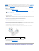
1 card fan 2 rubber grommets (4) 3 card fan cage 4 card fan power cable 7. Set the card fan aside in a secure location. CAUTION: Ensure that the fan power cable is correctly routed through the opening in the lower-right corner of the fan cage. 8. To replace the card fan, orient the card fan power cable downward. Align the rubber grommets in the fan with the openings in each corner of the card fan cage, then pull the grommets through until they snap into place.
1 card fan cage 3 screw 2 tabs (4) 10. Replace the screw that secures the card fan cage to the chassis. 11. Connect the cables to the master I/O board (see Master I/O Board Components). 12. Replace any full-length expansion cards that you removed (see Installing PCI and PCI Express Cards). 13. Replace the computer cover (see Replacing the Computer Cover). 14. Connect your computer and devices to electrical outlets, and then turn them on. Replacing the Hard Drive Fan 1 1.
5. In succession, carefully pull on each corner of the hard drive fan to detach the rubber grommets securing the hard drive fan to the hard drive fan cage. 1 hard-drive fan 2 rubber grommets (4) 3 hard-drive fan cage 4 hard-drive fan cable 6. Set the hard drive fan aside in a secure location. 7. To replace the hard drive fan, orient the hard drive fan cable downward.
Back to Contents Page Replacing the Front I/O Panel Dell™ XPS™ 625 Service Manual WARNING: Before working inside your computer, read the safety information that shipped with your computer. For additional safety best practices information, see the Regulatory Compliance Homepage at www.dell.com/regulatory_compliance. 1. Follow the procedures in Before You Begin. 2. Remove the computer cover (see Replacing the Computer Cover). 3.
1 screws (2) 2 front I/O panel 10. To replace the front I/O panel, align the screw holes on the front I/O panel with the screw holes on the chassis, and replace the two screws. 11. Align the securing tabs on the front panel with the corresponding slots on the chassis and connect the FRONT_LED cable to the front panel. 1 front panel 3 securing tabs (4) 12. Rotate the front panel towards the computer until it snaps into place. 13. Replace the drive panel (see Replacing the Drive Panel) 14.
Back to Contents Page Replacing Lights Dell™ XPS™ 625 Service Manual Replacing the Front LED Board Replacing the Rear LED Board WARNING: Before working inside your computer, read the safety information that shipped with your computer. For additional safety best practices information, see the Regulatory Compliance Homepage at www.dell.com/regulatory_compliance. Replacing the Front LED Board NOTE: The front LED board is embedded on the front panel.
1 front panel 3 securing tabs (4) 2 FRONT_LED cable 8. Rotate the front panel towards the computer until it snaps into place. 9. Replace the drive panel (see Replacing the Drive Panel). 10. Replace the computer cover (see Replacing the Computer Cover). 11. Connect your computer and devices to electrical outlets, and then turn them on. Replacing the Rear LED Board 1. Follow the procedures in Before You Begin. 2. Remove the computer cover (see Replacing the Computer Cover). 3.
7. Route the REAR_LED_SENSOR cable under the system board and replace the system board (see Replacing the System Board). 8. Align the rear LED board with the metal tab on the chassis; then slide the rear LED board into place. 9. Replace the system board (see Replacing the System Board). 10. Replace the computer cover (see Replacing the Computer Cover). 11. Connect your computer and devices to electrical outlets, and then turn them on.
Back to Contents Page Replacing the Master I/O Board Dell™ XPS™ 625 Service Manual WARNING: Before working inside your computer, read the safety information that shipped with your computer. For additional safety best practices information, see the Regulatory Compliance Homepage at www.dell.com/regulatory_compliance. 1. Follow the procedures in Before You Begin. 2. Remove the computer cover (see Replacing the Computer Cover). 3. Remove the card fan cage (see Replacing the Card Fan). 4.
Back to Contents Page Replacing Memory Module(s) Dell™ XPS™ 625 Service Manual WARNING: Before working inside your computer, read the safety information that shipped with your computer. For additional safety best practices information, see the Regulatory Compliance Homepage at www.dell.com/regulatory_compliance. 1. Follow the procedures in Before You Begin. 2. Remove the computer cover (see Replacing the Computer Cover). 3. Locate the memory modules on the system board (see System Board Components).
9. Connect your computer and devices to electrical outlets, and then turn them on. If the message appears stating that memory size has changed, press to continue. 10. Log on to your computer. 11. Right-click the My Computer icon on your Microsoft® Windows® desktop and click Properties. 12. Click the General tab. 13. To verify that the memory is installed correctly, check the amount of memory (RAM) listed.
Back to Contents Page Replacing the Power Supply Dell™ XPS™ 625 Service Manual WARNING: Before working inside your computer, read the safety information that shipped with your computer. For additional safety best practices information, see the Regulatory Compliance Homepage on www.dell.com at the following location: www.dell.com/regulatory_compliance. WARNING: To guard against electrical shock, always unplug your computer from the electrical outlet before removing the cover. 1.
14. Reattach each of the DC power cables that were previously connected, carefully rerouting them as you found them. 15. Replace the computer cover (see Replacing the Computer Cover). 16. Connect your computer and devices to electrical outlets, and then turn them on.
Back to Contents Page System Setup Dell™ XPS™ 625 Service Manual Overview Entering System Setup System Setup Options Boot Sequence Overview Use System Setup: l To change the system configuration information after you add, change, or remove any hardware in your computer. l To set or change a user-selectable option such as the user password. l To read the current amount of memory or set the type of hard drive installed.
System Date Displays the system date. System Time Displays the system time. System Info Displays the system model name. BIOS Info Display the BIOS revision. Service Tag Displays the system service tag. Asset Tag Displays the asset tag. Memory Installed Displays the total memory size. Memory Technology Displays the type of memory used in the system. Processor Type Displays the type of processor. Processor Speed Displays the speed of the processor.
Boot Sequence This feature allows you to change the boot sequence for the bootable devices installed on your computer. Option Settings l Diskette Drive — The computer attempts to boot from the floppy drive. If the floppy disk in the drive is not bootable, if no floppy disk is in the drive, or if there is no floppy drive installed in the computer, the computer attempts to boot from the next bootable device in the boot sequence. l Hard Drive — The computer attempts to boot from the primary hard drive.
Back to Contents Page
Back to Contents Page Replacing the System Board Dell™ XPS™ 625 Service Manual WARNING: Before working inside your computer, read the safety information that shipped with your computer. For additional safety best practices information, see the Regulatory Compliance Homepage at www.dell.com/regulatory_compliance 1. Follow the procedures in Before You Begin. 2. Remove the computer cover (see Replacing the Computer Cover). WARNING: The processor heat sink can get very hot during normal operation.
15. Reconnect all cables to the system board. 16. Replace the computer cover (see Replacing the Computer Cover). 17. Connect your computer and devices to electrical outlets, and then turn them on. 18. Flash the system BIOS, as needed. NOTE: For information on flashing the system BIOS, see the Dell Support website at support.dell.com.
Back to Contents Page Technical Overview Dell™ XPS™ 625 Service Manual Inside View of Your Computer System Board Components Master I/O Board Components WARNING: Before working inside your computer, read the safety information that shipped with your computer. For additional safety best practices information, see the Regulatory Compliance Homepage at www.dell.com/regulatory_compliance.
7 master I/O board USB connector (MASTER IO BD) 8 front panel IEEE connector (FP_1394) 9 internal S/PDIF connector (INTERNAL SPDIF) 10 front panel audio (FP_AUDIO) 11 PCI card slot (PCI SLOT6) 12 PCI-Express x1 card slot (PCI-E X1 SLOT5) 13 PCI card slot (PCI SLOT4) 14 PCI-Express x16 card slot (PCI-E X16 SLOT3) 15 PCI-Express x8 card slot (PCI-E X8 SLOT2) 16 PCI-Express x16 card slot (PCI-E X16 SLOT1) 17 battery socket (BATTERY1) 18 password reset jumper (PSWD1) 19 power connector (12V_ATXP)