Dell™ XPS™ 730/730X Service Manual Model DCDO w w w. d e l l . c o m | s u p p o r t . d e l l .
Notes, Cautions, and Warnings NOTE: A NOTE indicates important information that helps you make better use of your computer. CAUTION: A CAUTION indicates potential damage to hardware or loss of data if instructions are not followed. WARNING: A WARNING indicates a potential for property damage, personal injury, or death. If you purchased a Dell™ n Series computer, any references in this document to Microsoft® Windows® operating systems are not applicable.
Contents 1 Technical Overview . . . . . . . . . . . . . . . . . . Inside View of Your Computer . . . . . . . . . . . . . . . 7 . . . . . . . . . . . . . . . . 8 . . . . . . . . . . . . . . . . . . . 8 System Board Components Dell™ XPS™ 730 Dell XPS 730X . 2 7 . . . . . . . . . . . . . . . . . . . 10 Master Control Board . . . . . . . . . . . . . . . . . . 12 Before You Begin . . . . . . . . . . . . . . . . . . . 13 Technical Specifications Recommended Tools . . . . . . . . . . . . . .
Replacing the Theater Lighting Card . . . . . . . . . . 6 Replacing Memory Module(s) 7 Replacing a PCI/PCI Express Card . . . . . . . . . . . . Removing a PCI Express Graphics Card From a Multi Graphics Card Configuration . . . . . . . . . . . 8 Replacing Drives 35 . . . . . . . . . . . . . . . 9 62 . . . . . . . . . Replacing the Liquid Cooling Heat Sink Assembly Installing the Processor 4 Contents 51 . . . . . . . . . . . .
11 Replacing Fans . . . . . . . . . . . . . . . . . . . . Removing the Card Slot and Processor Fan Shrouds . . . . . . . . . . . . . . . 77 77 Replacing the Card Slot Fan Assembly . . . . . . . 77 Replacing the Processor Fan Assembly . . . . . . 79 . . . . . . . . . . . 80 Replacing the Hard Drive Fan 12 Replacing the Master Control Board . . . 83 13 Replacing the System Board . . . . . . . . . . 85 14 Replacing the Power Supply . . . . . . . . . . 89 . . . . . . . . . . . . . . .
Clearing CMOS Settings . 6 Contents . . . . . . . . . . . . . . .
1 Technical Overview WARNING: Before working inside your computer, read the safety information that shipped with your computer. For additional safety best practices information, see the Regulatory Compliance Homepage at www.dell.com/regulatory_compliance.
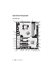
System Board Components Dell™ XPS™ 730 2 1 29 3 4 5 28 6 27 7 26 25 8 24 23 9 22 10 21 20 8 19 18 Technical Overview 17 16 15 14 13 12 11
1 CPU socket 2 system board CPU fan header 3 DIMMs 0 and 1 (DIMM 0-1) 4 DIMMs 2 and 3 (DIMM 2-3) 5 ATX power connector (ATX_PWR) 6 IDE connector (IDE) 7 SATA ports 3-6 (SATA 3-6) 8 floppy header (FLOPPY) 9 BIOS debug codes (PORT 80 DECODER) 10 SATA ports 1-2 (SATA 1-2) 11 font panel connector (FRONT PNL) 12 serial port header (SERIAL PORT)-unused 13 reset CMOS jumper (RESET CMOS) 14 internal USB header 1 (USB) 15 internal USB header 2 (USB) 16 1394 header 17 battery socket 18
Dell XPS 730X 2 1 20 3 4 5 6 7 19 8 18 17 16 15 14 10 Technical Overview 13 12 11 10 9
1 CPU socket 2 system board CPU fan header 3 DIMMs 1, 3, and 5 4 ATX power connector (ATX_PWR) 5 IDE connector (IDE) 6 SATA port 4 (SATA 4) 7 battery socket 8 SATA ports 1-3 (SATA 1-3) 9 internal USB header 1 (USB) 10 internal USB header 2 (USB) 11 internal USB header 3 (USB) 12 1394 header 13 PCI slot 1 (PCI SLOT 1) 14 front panel audio header (FP Audio) 15 PCIe slot 5 (PCI_E5) 16 PCIe slot 4 (PCI_E4) 17 PCIe slot 3 (PCI_E3) 18 PCIe slot 2 (PCI_E2) 19 PCIe slot 1 (PCI_E1) 2
Master Control Board 1 2 3 4 5 6 7 16 15 14 12 13 12 11 10 9 1 internal LED header (INTERNAL_LED) 2 power header (POWER) 3 front top LED header (FRONT_TOP_LED) 4 front bottom right LED IO header (BOT_RT_LED) 5 PCI cage fan header (FAN_CAGE) 6 power button board header (CON_PWR_BTN) 7 rear PCI LED header (REAR_PCI_LED) 8 hard drive fan (FAN_HDD) 9 factory defaults jumper (FACTORY_DEFAULT) 10 internal USB headers (USB_FLEXBAY 1-2) 11 system AC power LED indicator 12 USB
Technical Overview 13
Technical Overview
2 Before You Begin This chapter provides procedures for removing and installing the components in your computer. Unless otherwise noted, each procedure assumes that the following conditions exist: • You have performed the steps in "Turning Off Your Computer" on page 13 and "Safety Instructions" on page 14. • You have read the safety information that ships with your computer. • A component can be replaced or—if purchased separately—installed by performing the removal procedure in reverse order.
Safety Instructions Use the following safety guidelines to help protect your computer from potential damage and to help to ensure your own personal safety. WARNING: Before working inside your computer, read the safety information that shipped with your computer. For additional safety best practices information, see the Regulatory Compliance Homepage at www.dell.com/regulatory_compliance. CAUTION: Only a certified service technician should perform repairs on your computer.
Replacing the Computer Stand 3 WARNING: Your computer is heavy and can be difficult to maneuver. Seek assistance before attempting to lift, move, or tilt the computer and always lift correctly to avoid injury; avoid bending over while lifting. WARNING: The computer stand should be installed at all times to ensure maximum system stability. Failure to install the stand could result in the computer tipping over, potentially resulting in bodily injury or damage to the computer.
4 To replace the computer stand, perform the removal procedure in reverse order.
Replacing the Computer Cover 4 WARNING: Before working inside your computer, read the safety information that shipped with your computer. For additional safety best practices information, see the Regulatory Compliance Homepage at www.dell.com/regulatory_compliance. WARNING: To guard against electrical shock, always unplug your computer from the electrical outlet before removing the cover.
1 2 3 4 1 computer cover 2 cover release latch 3 cover hinge tabs 4 stabilizing feet (closed) 3 With the cover release latch pulled back, grip the sides of the cover, then pivot the top of the cover up and away from the computer. 4 Slide the cover forward and up to remove it from the hinge slots, then set it aside in a secure and protected location. 5 To replace the computer cover, perform the removal procedure in reverse order.
5 Replacing the Theater Lighting Unit WARNING: Before working inside your computer, read the safety information that shipped with your computer. For additional safety best practices information, see the Regulatory Compliance Homepage at www.dell.com/regulatory_compliance. WARNING: To guard against electrical shock, always unplug your computer from the electrical outlet before removing the cover.
1 2 1 captive screws 2 batteries 3 Remove the two captive screws and lift the cover of the battery unit. 4 Replace the batteries with a new pair. 5 Replace the cover of the battery unit and ensure that the screws are secure. 6 Replace the computer cover (see "Replacing the Computer Cover" on page 17). 7 Connect your computer and devices to electrical outlets, and then turn them on. Replacing the Theater Lighting Card 1 Follow the procedures in "Before You Begin" on page 13.
1 2 1 theater lighting card 2 theater lighting card connector 3 Disconnect the theater lighting card connector. 4 Remove the screw securing the theater lighting card to the chassis and lift the card out of the slot. 5 Replace the theater lighting card in its slot and tighten the screw. 6 Replace the computer cover (see "Replacing the Computer Cover" on page 17).
7 Connect your computer and devices to electrical outlets, and then turn them on.
Replacing Memory Module(s) 6 WARNING: Before working inside your computer, read the safety information that shipped with your computer. For additional safety best practices information, see the Regulatory Compliance Homepage at www.dell.com/regulatory_compliance. 1 Follow the procedures in "Before You Begin" on page 13. 2 Remove the computer cover (see "Replacing the Computer Cover" on page 17). 3 Locate the memory modules on the system board (see "System Board Components" on page 8).
Dell™ XPS™ 730: B A A matched pair of modules in DIMM connectors 0 and 1 24 Replacing Memory Module(s) B matched pair of memory modules in DIMM connectors 2 and 3
Dell XPS 730X: 7 Align the notch on the bottom of the module with the tab in the connector. 3 2 1 4 1 cutouts (2) 2 memory module 3 notch 4 tab CAUTION: To avoid damage to the memory module, press the module straight down into the connector while you apply equal force to each end of the module. 8 Insert the module into the connector until the module snaps into position.
If you insert the module correctly, the securing clips snap into the cutouts at each end of the module. 9 Replace the computer cover (see "Replacing the Computer Cover" on page 17). 10 Connect your computer and devices to electrical outlets, and then turn them on. If the message appears stating that memory size has changed, press to continue. 11 Log on to your computer. 12 Right-click the My Computer icon on your Microsoft® Windows® desktop and click Properties. 13 Click the General tab.
7 Replacing a PCI/PCI Express Card WARNING: Before working inside your computer, read the safety information that shipped with your computer. For additional safety best practices information, see the Regulatory Compliance Homepage at www.dell.com/regulatory_compliance. NOTE: If a graphics card is installed in each of the PCIe x16 card slots in the multigraphics configuration, the PCIe x1 and one PCI card slot are not accessible for use.
Removing a PCI Express Graphics Card From a Multi Graphics Card Configuration NOTE: This section deals with dual and triple configurations of PCIe x16 graphics cards only. For removal of any other type of PCI or PCIe cards, see "Replacing the PCI and PCI Express Cards" on page 35. 1 Follow the procedures in "Before You Begin" on page 13. 2 Remove the computer cover (see "Replacing the Computer Cover" on page 17).
4 Disconnect any cables connected to the card. 5 Remove the captive screws on top of the PCI card fan shroud and remove the shroud. 6 Remove the card retention screw(s) on the top of the card retainer at the appropriate card slot and pivot the card retainer back through the chassis wall.
7 Press the securing tab (if present) on the system board connector as you grasp the card by its top corners, and then ease the card straight out of the connector. 1 2 3 1 PCIe x16 card 3 PCIe x16 card slot 2 securing tab 8 Install a filler bracket in the empty card-slot opening. If you are replacing the card, see "Installing Graphics Cards for Multi Graphics Card" on page 31. NOTE: Installing filler brackets over empty card-slot openings is necessary to maintain FCC certification of the computer.
Installing Graphics Cards for Multi Graphics Card NOTE: To upgrade to or downgrade from a dual- or triple-graphics card configuration, you may need additional parts that can be ordered from Dell. This section pertains to using dual and triple PCIe graphics cards to take advantage of NVIDIA’s SLI (Scalable Link Interface). For installation of other types of PCI or PCIe cards, see "Replacing a PCI/PCI Express Card" on page 27.
1 3 2 4 1 retention screw 2 card retainer 3 alignment guide 4 fan bracket 6 Prepare the cards for installation. See the documentation that came with the cards for information on configuring them, making internal connections, or otherwise customizing them for your computer. 7 Position each card so that it is aligned with the slot and that the securing tab (if present) is aligned with the slot. NOTE: If the card is full length, insert the card guide into the alignment slot on the fan bracket.
1 2 3 1 PCIe x16 card 3 PCIe x16 card slot 2 securing tab CAUTION: Ensure that you release the securing tab to seat the card. If the card is not installed correctly, you may damage the system board. Gently pull the securing tab (if present) and place the card in the connector. Press down firmly and ensure that the card is fully seated in the slot. CAUTION: Do not route card cables over or behind the cards.
1 2 3 1 graphics card bridge 3 dual-PCIe graphics cards 2 power connectors (2) 11 If present, lower the graphics card bridge that lays over the installed cards and snap it into place. 12 Replace the computer cover (see "Replacing the Computer Cover" on page 17), reconnect the computer and devices to electrical outlets, and then turn them on.
Replacing the PCI and PCI Express Cards CAUTION: To avoid electrostatic discharge and damage to internal components, ground yourself by using a wrist grounding strap or by periodically touching an unpainted metal surface on the computer chassis. CAUTION: If your computer came with a PCI graphics card installed, removal of the card is not necessary when installing additional graphics cards; however, the card is required for troubleshooting purposes.
1 3 2 4 1 retention screw 2 card retainer 3 alignment guide 4 fan bracket 6 Press the securing tab (if present) on the system board connector as you grasp the card by its top corners, and then ease the card out of the connector. NOTE: If the card is full length, press the securing tab on the end of the alignment guides on the fan bracket.
1 2 3 1 PCIe x16 card 3 PCIe x16 card slot 2 securing tab 7 Install a filler bracket in the empty card-slot opening. If you are replacing the card, see "Replacing a PCI/PCI Express Card" on page 27. NOTE: Installing filler brackets over empty card-slot openings is necessary to maintain FCC certification of the computer. The brackets also keep dust and dirt out of your computer. CAUTION: Do not route card cables over or behind the cards.
13 Press down the tab on the top of the graphics card bridge at the appropriate card slot and pivot the graphics card bridge back through the chassis wall. 1 3 2 4 1 retention screw 2 card retainer 3 alignment guide 4 fan bracket 14 Remove the filler bracket or existing card (see "Replacing the PCI and PCI Express Cards" on page 35) to create a card-slot opening. 15 Prepare the card for installation.
NOTE: If the card is full length, insert the card guide into the alignment slot on the fan bracket. 1 2 3 1 PCIe x16 card 3 PCIe x16 card slot 2 securing tab CAUTION: Ensure that you release the securing tab to seat the card. If the card is not installed correctly, you may damage the system board. 17 Gently pull the securing tab (if present) and place the card in the connector. Press down firmly and ensure that the card is fully seated in the slot.
2 3 1 6 4 5 1 card connector (seated) 2 card connector (not seated) 3 bracket properly aligned within slot 4 bracket improperly aligned outside of slot 5 alignment bar 6 alignment guide CAUTION: Do not route card cables over or behind the cards. Cables routed over the cards can prevent the computer cover from closing properly or cause damage to the equipment. CAUTION: An incorrectly attached graphics power cable may result in degraded graphics performance.
19 Rotate the graphics card bridge back into its original position; push its tip so that its tab clicks into place. 20 If present, lower the graphics card bridge that lays over the installed cards and snap it into place. 21 Replace the computer cover (see "Replacing the Computer Cover" on page 17), reconnect the computer and devices to electrical outlets, and then turn them on. 22 Install any drivers required for the card as described in the card documentation.
42 Replacing a PCI/PCI Express Card
8 Replacing Drives WARNING: Before working inside your computer, read the safety information that shipped with your computer. For additional safety best practices information, see the Regulatory Compliance Homepage at www.dell.com/regulatory_compliance. Replacing a Hard Drive WARNING: To guard against electrical shock, always unplug your computer from the electrical outlet before removing the cover.
Dell™ XPS™ 730: 1 1 44 2 power cable Replacing Drives 2 data cable
Dell XPS 730X: 1 1 2 power cable 2 data cable 4 Press the blue tabs on each side of the hard drive bracket toward each other and slide the drive up and out of the hard drive bay.
1 2 3 1 blue tabs (2) 3 hard drive bay 2 hard drive NOTE: If a hard drive bracket is installed inside the hard drive bay, remove the bracket before you install a new hard drive. 5 Prepare the new hard drive for installation and check the documentation for the hard drive to verify that the drive is configured for your computer. NOTE: If the hard drive you are installing does not have the hard drive bracket attached, use your original hard drive bracket; snap the bracket onto the new drive.
3.
2.
6 Verify that the hard drive bay is empty and unobstructed. 7 Slide the hard drive into the hard drive bay until it clicks securely into place. 1 2 1 hard drive 2 hard drive bay CAUTION: Ensure that all connectors are properly cabled and firmly seated. 8 Connect the power cable to the hard drive. 9 Connect the hard drive data cable to the hard drive.
Dell XPS 730: 2 1 1 50 power cable Replacing Drives 2 data cable
Dell XPS 730X: 2 1 1 power cable 2 data cable 10 Replace the computer cover (see "Replacing the Computer Cover" on page 17). 11 Connect the computer and devices to electrical outlets, and turn them on. See the documentation that came with the drive for instructions on installing any software required for drive operation. Replacing the Drive Panel 1 Follow the procedures in "Before You Begin" on page 13. 2 Remove the computer cover (see "Replacing the Computer Cover" on page 17).
3 Grasp the drive release latch and slide it towards the base of the computer until the drive panel snaps open. 1 3 2 1 drive release latch 3 drive panel tabs 2 drive panel 4 Pivot the drive panel outward and lift it from its side hinges. 5 Set the drive panel aside in a secure location. 6 To install the new drive panel, align the drive panel tabs with the side door hinges.
3 1 2 1 drive release latch 3 drive panel tabs 2 drive panel 7 Rotate the drive panel toward the computer until it snaps into place on the drive panel. 8 Replace the computer cover (see "Replacing the Computer Cover" on page 17). Replacing a Floppy Drive (XPS 730 Only) 1 Follow the procedures in "Before You Begin" on page 13. 2 Remove the computer cover (see "Replacing the Computer Cover" on page 17). 3 Remove the drive panel (see "Replacing the Drive Panel" on page 51).
2 1 1 power cable 2 floppy drive data cable 5 Slide the drive release latch towards the base of the computer to release the shoulder screw, and then slide the drive out of the drive bay.
1 2 1 drive release latch 2 floppy drive 6 If no screws are attached to the new floppy drive, check the inside of the drive panel for shoulder screws. If screws are present, attach the screws to the new drive.
1 floppy drive 2 shoulder screws (4) 7 Slide the floppy drive into the drive bay until it clicks into place. 1 2 1 drive release latch 2 floppy drive 8 Connect the power and data cables to the back of the floppy drive. 9 Check all cable connections and fold cables out of the way to avoid blocking airflow between the fan and cooling vents. 10 Replace the drive panel (see "Replacing the Drive Panel" on page 51). 11 Replace the computer cover (see "Replacing the Computer Cover" on page 17).
See the documentation that came with the drive for instructions on installing any software required for drive operation. 13 Enter system setup (see "System Setup" on page 97), and select the appropriate Diskette Drive option. Replacing an Optical Drive 1 Follow the procedures in "Before You Begin" on page 13. 2 Remove the computer cover (see "Replacing the Computer Cover" on page 17). 3 Remove the drive panel (see "Replacing the Drive Panel" on page 51).
1 2 1 data cable 2 power cable 5 Slide the drive release latch towards the base of the computer to release the shoulder screw, and then slide the optical drive out of the drive bay.
1 2 1 drive release latch 2 optical drive 6 To replace the optical drive, prepare the drive for installation and check the documentation that accompanied the drive to verify that the drive is configured for your computer. NOTE: If you are installing an IDE drive, configure the drive for the cable select setting. 7 If no screws are attached to the drive, check the inside of the drive panel for screws and, if screws are present, attach the screws to the new drive.
1 2 1 optical drive 2 shoulder screws (3) 8 Gently slide the drive into the drive bay until you hear a click or feel the drive securely installed.
9 Attach the power and data cables to the optical drive. To locate the system board connector, see "System Board Components" on page 8. 1 2 1 power cable 2 data cable 10 Check all cable connections and fold cables out of the way to avoid blocking airflow between the fan and cooling vents. 11 Replace the drive panel (see "Replacing the Drive Panel" on page 51). 12 Replace the computer cover (see "Replacing the Computer Cover" on page 17).
See the documentation that came with the drive for instructions on installing any software required for drive operation. 14 Enter system setup (see "System Setup" on page 97) and select the appropriate Drive option. Replacing a Media Card Reader 1 Follow the procedures in "Before You Begin" on page 13. 2 Remove the computer cover (see "Replacing the Computer Cover" on page 17). 3 Remove the drive panel (see "Replacing the Drive Panel" on page 51).
5 Slide the drive release latch towards the base of the computer to release the shoulder screw, and then slide the media card reader out of the drive bay.
6 If no screws are attached to the new Media Card Reader, check the inside of the drive panel for shoulder screws. If screws are present, attach the screws to the new card reader. 1 2 1 media card reader 2 shoulder screws (4) 7 Slide the Media Card Reader into the drive bay until it clicks into place.
1 2 1 drive release latch 2 media card reader 8 Attach the cable to the back of the Media Card Reader. 9 Check all cable connections and fold cables out of the way to avoid blocking airflow between the fan and cooling vents. 10 Replace the drive panel (see "Replacing the Drive Panel" on page 51). 11 Replace the computer cover (see "Replacing the Computer Cover" on page 17). 12 Connect your computer and devices to their electrical outlets, and turn them on.
13 Enter system setup (see "System Setup" on page 97) and select the appropriate USB for FlexBay option.
9 Replacing the Heat Sink Assembly WARNING: Before working inside your computer, read the safety information that shipped with your computer. For additional safety best practices information, see the Regulatory Compliance Homepage at www.dell.com/regulatory_compliance. CAUTION: Do not perform the following steps unless you are familiar with hardware removal and replacement. Performing these steps incorrectly could damage your system board. For technical service, see the Setup Guide.
3 1 2 1 fan power connector 3 captive screws (4) 2 LED circuit board CAUTION: The processor heat sink is attached to the processor fan shroud. When you remove the processor fan shroud, lay it upside down or on its side to avoid damaging the heat sink thermal interface. CAUTION: Ensure that adequate thermal grease is applied to the top of the processor. Thermal grease is critical for ensuring adequate thermal bonding, which is a requirement for optimal processor operation.
Replacing the Liquid Cooling Heat Sink Assembly WARNING: The liquid cooling assembly is responsible for cooling the system board chipset in addition to the CPU. If the liquid cooling assembly is replaced with an assembly other than the original, a cooling solution must be installed to avoid overheating the chipset. Failure to install a cooling solution, either thirdparty or Dell provided, may result in damage to your system and render the system inoperable.
2 1 1 liquid cooling assembly 2 captive screws CAUTION: Ensure that adequate thermal grease is applied to the top of the processor. Thermal grease is critical for ensuring adequate thermal bonding, which is a requirement for optimal processor operation. 6 To install the liquid cooling heat sink assembly, apply thermal grease to the top of the processor as needed.
Replacing the Heat Sink Assembly 71
72 Replacing the Heat Sink Assembly
Replacing the Processor 10 WARNING: Before working inside your computer, read the safety information that shipped with your computer. For additional safety best practices information, see the Regulatory Compliance Homepage at www.dell.com/regulatory_compliance. CAUTION: Do not perform the following steps unless you are familiar with hardware removal and replacement. Performing these steps incorrectly could damage your system board. For technical service, see the Setup Guide.
Removing the Processor 1 2 3 4 1 processor cover 2 processor 3 socket 4 release lever CAUTION: When removing or replacing the processor, do not touch any of the pins inside the socket or allow any object to fall on the pins in the socket. 7 Lift the processor to remove it from the socket, place it aside in a safe and secure place. Leave the release lever extended in the release position so that the socket is ready for the new processor.
Installing the Processor 1 2 3 9 4 5 6 8 7 1 processor cover 2 tab 3 processor 4 socket 5 center cover latch 6 release lever 7 front alignment-notch 8 processor pin-1 indicator 9 rear alignment notch 9 If the release lever on the socket is not fully extended, move it to that position. CAUTION: Socket pins are delicate. To avoid damage, ensure that the processor is aligned properly with the socket, and do not use excessive force when you install the processor.
CAUTION: To avoid damage, ensure that the processor aligns properly with the socket, and do not use excessive force when you install the processor. 12 Set the processor lightly in the socket and ensure that the processor is positioned correctly. 13 When the processor is fully seated in the socket, close the processor cover, if applicable. Ensure that the tab on the processor cover is positioned underneath the center cover latch on the socket.
11 Replacing Fans WARNING: Before working inside your computer, read the safety information that shipped with your computer. For additional safety best practices information, see the Regulatory Compliance Homepage at www.dell.com/regulatory_compliance. WARNING: To guard against likelihood of electric shock, laceration by moving fan blades or other unexpected injuries, always unplug your computer from the electrical outlet before removing the cover.
3 2 1 1 cage housing 3 screws (2) 2 fan cage 7 To install the card slot fan assembly, connect the fan cable to the FAN_CAGE connector on the system board (see "Master Control Board" on page 12). 8 Align the fan cage tabs with the slots in the chassis. Insert the tabs and push the cage towards the front of the chassis. 9 Screw in the fan retention screws on the front and back of the fan cage. 10 Replace any expansion cards that you removed (see "Replacing a PCI/PCI Express Card" on page 27).
12 Replace the computer cover (see "Replacing the Computer Cover" on page 17). 13 Connect your computer and devices to electrical outlets, and then turn them on. Replacing the Processor Fan Assembly 1 Remove the card slot fan shroud (see "Removing the Card Slot and Processor Fan Shrouds" on page 77).
2 Remove the processor fan shroud (see "Removing the Card Slot and Processor Fan Shrouds" on page 77) 3 Disconnect the fan cable from the FAN_CPU_FRONT connector on the Master Control Board (see "Master Control Board" on page 12). 4 Loosen the captive screws securing the processor fan shroud to the chassis, then rotate the shroud back. 5 To Install the processor fan assembly, align the hinge slots on the processor fan shroud with the hinge guides on the chassis.
1 2 1 hard-drive fan release latch 2 hard drive fan 6 To install the hard drive fan, slide the fan between the hard drive bays until it snaps into place. 7 Connect the fan cable to the FAN_HDD connector on the Master Control Board (see "Master Control Board" on page 12). 8 Replace the computer cover (see "Replacing the Computer Cover" on page 17). 9 Connect your computer and devices to electrical outlets, and then turn them on.
82 Replacing Fans
12 Replacing the Master Control Board WARNING: Before working inside your computer, read the safety information that shipped with your computer. For additional safety best practices information, see the Regulatory Compliance Homepage at www.dell.com/regulatory_compliance 1 Follow the procedures in "Before You Begin" on page 13. 2 Remove the computer cover (see "Replacing the Computer Cover" on page 17). 3 Remove the fan shrouds (see "Removing the Card Slot and Processor Fan Shrouds" on page 77).
8 Lift the master control board out. 1 2 1 master control board 2 Screws (3) 9 To replace the master control board, Orient the board on the metal tray. 10 Replace the three screws to secure the master control board assembly to the metal tray. 11 Reconnect all cables to the master control board. 12 Replace the processor fan assembly (see "Replacing the Processor Fan Assembly" on page 79). 13 Replace the card slot fan assembly (see "Replacing the Card Slot Fan Assembly" on page 77).
Replacing the System Board 13 WARNING: Before working inside your computer, read the safety information that shipped with your computer. For additional safety best practices information, see the Regulatory Compliance Homepage at www.dell.com/regulatory_compliance 1 Follow the procedures in "Before You Begin" on page 13. 2 Remove the computer cover (see "Replacing the Computer Cover" on page 17). 3 Remove any full-length expansion cards (see "Replacing the PCI and PCI Express Cards" on page 35).
1 2 4 3 1 screws (2) 2 system board 3 metal tray 4 tabs CAUTION: The system board and metal tray are connected and are removed as one piece. 7 Carefully, lift the system board assembly up and out of the computer. CAUTION: If you are replacing the system board, visually compare the replacement system board to the existing system board to make sure that you have the correct part.
9 Orient the system board assembly by aligning the notches on the bottom of the assembly with the tabs on the computer. 10 Slide the system board assembly toward the back of the computer until the assembly clicks into place. 11 Replace the two screws to secure the system board assembly to the chassis. 12 Replace any expansion cards that you removed (see "Replacing a PCI/PCI Express Card" on page 27). 13 Replace any additional components that you removed from the system board.
88 Replacing the System Board
Replacing the Power Supply 14 WARNING: Before working inside your computer, read the safety information that shipped with your computer. For additional safety best practices information, see the Regulatory Compliance Homepage on www.dell.com at the following location: www.dell.com/regulatory_compliance. WARNING: To guard against electrical shock, always unplug your computer from the electrical outlet before removing the cover. 1 Follow the procedures in "Before You Begin" on page 13.
1 2 1 screws (4) 2 hard drive bays 7 Remove the four screws that attach the power supply to the back of the computer chassis. 8 Disconnect the power supply harness from the power supply by depressing the two tabs and pulling the harness away from the power supply.
1 1 power supply screws (4) 9 Slide the power supply towards the front of the computer to free it from the securing tabs on the computer chassis. 10 Slide the power supply toward the hard drive bay area, so that it will clear the protruding lip of the chassis and lift the power supply from the computer. 11 To replace the power supply, slide the new power supply into place, ensuring that the tabs on the rear wall of the computer chassis latch into place.
12 Replace the four screws that secure the power supply to the back of the computer chassis. 13 Reconnect the power supply harness to the power supply. 14 Replace the two hard drive bays. 15 Replace all hard drives installed in the interior hard drive bays (see "Replacing a Hard Drive" on page 43). 16 Replace the hard drive fan, if applicable (see "Replacing the Hard Drive Fan" on page 80). 17 Reconnect each of the DC power cables that were previously connected, carefully rerouting them as you found them.
15 Replacing the Battery WARNING: Before working inside your computer, read the safety information that shipped with your computer. For additional safety best practices information, see the Regulatory Compliance Homepage at www.dell.com/regulatory_compliance. WARNING: A new battery can explode if it is incorrectly installed. Replace the battery only with the same or equivalent type recommended by the manufacturer. Discard used batteries according to the manufacturer’s instructions.
5 Carefully press the battery release lever away from the battery and the battery will pop out. 6 Remove the battery from the system and properly dispose of the battery. 7 Insert the new battery into the socket with the side labeled "+" facing up, then snap the battery into place. 1 2 1 battery (positive side) 2 battery release lever 8 Replace the computer cover (see "Replacing the Computer Cover" on page 17). 9 Connect your computer and devices to electrical outlets, and then turn them on.
16 System Setup Overview Use System Setup to: • change the system configuration information after you add, change, or remove any hardware in your computer. • set or change a user-selectable option such as the user password. • read the current amount of memory or set the type of hard drive installed. Before you use System Setup, it is recommended that you write down the system setup screen information for future reference.
System Setup Options—Dell™ XPS™ 730 NOTE: Depending on your computer and installed devices, the items listed in this section may, or may not appear exactly as listed. Main System Date Displays the current date in the mm:dd:yy format. System Time Displays the time in the hh:mm:ss format. SATA 0 Displays the SATA 0 drive integrated in the system. SATA 1 Displays the SATA 1 drive integrated in the system.
Power ACPI Suspend Type Specifies the ACPI suspend type. The default is S3. Auto Power On Allows you to enable or disable an alarm to turn on the computer automatically. AC Recovery Specifies the behaviour of the system after recovering from a power loss. • Power on — The computer turns on after it recovers from a power failure. • Power off — The computer remains powered off. • Last state— The computer returns the power state it was in before the power failure.
Exit Exit Options Provides options to Save Changes and Exit, Discard Changes and Exit, Load Optimal Defaults, and Discard Changes. System Setup Options—Dell XPS 730X System Information Product Name XPS 730X. BIOS Version Displays the BIOS version number and date information. Input Service tag Allows you to input the service tag. Service Tag Displays the service tag of the computer. Asset Tag Displays the Asset tag of the computer. Memory Installed Indicates amount of memory installed.
System Time (hh:mm:ss) Displays the current time. System Date (mm:dd:yy) Displays thecurrent date. SATA 1 Displays the SATA 1 drive integrated in the system. SATA 2 Displays the SATA 2 drive integrated in the system. SATA 3 Displays the SATA 3 drive integrated in the system. SATA 4 Displays the SATA 4 drive integrated in the system. SATA 5 Displays the SATA 5 drive integrated in the system. SATA 6 Displays the SATA 6 drive integrated in the system.
CPU Configuration XD Bit Capability Enable XD Bit Capability to allow the processor to distinguish between the bits of code that should be executed and the ones that cannot be executed. C1E Support The Enhanced Halt State (C1E) reduces the processor speed down to its lowest multiplier when the load on the processor is reduced. Max CPUID Value Limit Limits the max value the processor standard CPUID function will support.
Power Management Setup Suspend Mode This option sets the energy-saving mode of the ACPI function. AC Recovery This option sets what action the PC takes when power is restored. Remote Wakeup This option sets the system to wake up from an onboard LAN, PCIE-X1 LAN card, or a PCI LAN card. Auto Power On This option allows the computer to start up at a certain time. Frequency/Voltage Control QPI Links SPeed Allows you to change the QuickPath Interconnect (QPI) Links to full-speed or slow-mode.
Boot Sequence This feature allows you to change the boot sequence for the bootable devices installed on your computer. Option Settings • Hard Drive — The computer attempts to boot from the primary hard drive. If no operating system is on the drive, the computer attempts to boot from the next bootable device in the boot sequence. • CD Drive — The computer attempts to boot from the CD drive.
If you wait too long and the operating system logo appears, continue to wait until you see the Microsoft Windows desktop, then shut down your computer and try again. 4 At the Boot Device Menu, use the up- and down- arrow keys or press the appropriate number on the keyboard to highlight the device that is to be used for the current boot only, and then press . For example, if you are booting to a USB memory key, highlight USB Flash Device and press .
Dell™ XPS™ 730 Dell™ XPS™ 730X 7 Place the jumper on pins 1 and 2 and wait for 5 seconds. 8 Move the jumper back onto pins 2 and 3. 9 Close the computer cover (see "Replacing the Computer Cover" on page 17). 10 Connect your computer and devices to electrical outlets, and then turn them on.
System Setup 107
System Setup
System Setup 109
System Setup