U CONTENTS I A U I A General recommendations 20 I A U I A Basic safety rules 20 I A Refrigerant circuits 29 U I A Recommendations 21 I A Indoor unit multifilar wiring diagram 29 U I A Range and accessories 21 I A Outdoor unit multifilar wiring diagram 30 I Size and weight 22 I Indoor/outdoor unit wiring diagrams 30 I Receiving the product 22 I Installation 31 I Handling 22 I Indoor unit installation 31 I Quick connector 23 I Outdoor unit installati
U GENERAL RECOMMENDATIONS After having removed the packing, check that the contents are intact and complete. In the event of non-compliance, contact the the appliance. Agency which sold you appliances should be installed by a qualified company in accordance with the laws and regulations in force in the country of installation.
U I A RECOMMENDATIONS Extraordinary maintenance Programmed maintenance always represents a saving in the running of the installation as well as preventing possible faults. To ensure trouble-free operation of the air-conditioner, it is recommended that it be inspected at least once a year, carrying out the following checks: - cleanliness of the heat exchange coils of both units Exposure control/personal protection Use protective clothes and suitable gloves; protect eyes and face.
I SIZE AND WEIGHT INDOOR UNIT Model L H P Weight 20 810 300 195 9 30 810 300 195 9 40 967 300 195 11 L H P OUTDOOR UNIT Model L H P Weight A B 20 660 500 230 34 420 264 30 660 500 230 35 420 264 L 40 800 640 280 52 550 310 H P A RECEIVING THE PRODUCT The air-conditioner comes in two packs protected by cardboard packaging and is accompanied by: - Instruction booklets for the user and the installer. - Warranty certificate. - Bar code labels.
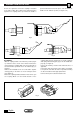
I QUICK CONNECTOR Components description A. B. C. D. Liquid line (high pressure) Vapor (low pressure) Cover Electrical I CONNECTION OF THE UNIT BASIC OPERATION The fast connector coupling uses a retractable sleeve and stem valve on the female half and a spring loaded poppet on the male side to create a safe, clean and quick Female separation of split air condotioning system with minimal fluid loss and air inclusion (see Figure 1). Fig.
I CONNECTION OF THE UNIT No tools are required to connect the coupling: a retractable sleeve and four latch pins hold the male and female halves together. The coupling valves open when the handle is pushed forward and locked into place, and shut when the handle is in the “full back” position (see figures 3-4). Fig. 2 Fig. 3 Fig. 4 TO CONNECT - With the coupling handle in the “full back” position (Figure 5), retract the release sleeve on the female and insert the male half into the coupling.
I CONNECTION OF THE UNIT TO DISCONNECT - Shut off the air conditioning unit and unplug the unit from the power outlet. - Wait five minutes for line pressures to equalize. - Disconnect the auxiliary electrical and condensate lines, if applicable. - On couplings equipped with spring loaded locking pins, depress the pin until it clears the coupling handle is pulled up. When the handle clears the locking pin, pull coupling handle to its “full back” position (see Figure 3).
U DESCRIPTION OF THE AIR-CONDITIONER I A alternating current; it ensures high performance, efficiency and low noise operation. The speed may be changed according to needs. The heat exchanger has a large surface area and consists of scored copper pipes and swirl-type aluminium fins. Regulation, control of functions, data interchange with the outdoor unit and diagnostics are governed by a microprocessor card. The air-conditioner is an appliance designed for small user systems.
U I A DESCRIPTION OF THE AIR-CONDITIONER OUTDOOR UNIT The high efficiency sliding-vane compressor is on double vibration-isolation flexible mountings and is activated by an electric motor powered by alternating current and fitted with an overload cutout. The large surface area exchange coil consists of scored copper pipes and aluminium fins. The air-conditioner is commanded and controlled by an electronic microprocessor system.
U TECHNICAL DATA CP 20 ARE 290 V/f/Hz Btu/h W Kcal/h W A Power supply Cooling capacity Consumption Current requirement E.E.R. Dehumidifying Heat output A CP 30 ARE 290 CF 40 ARE 290 CP 40 ARE 290 230/1/50 12000 3500 3020 1050 5,7 3.20 1.5 12000 3530 3030 1055 6 3.34 420 17000 5000 4310 1650 7.6 3.03 2.2 600 16320 4800 4137 1570 7.6 3.0 1.9 19720 5800 5000 1860 8.1 3.11 600 650 37 650 37 8013 2350 2025 740 3.9 3.18 1.3 8422 2470 2130 690 3.5 3.57 200 12000 3520 3035 1090 5.7 3.23 1.
I A REFRIGERANT CIRCUITS Heating/Cooling Cooling HEATING COOLING Legend Condenser coil Cooler coil General filter Throttling part (capillary) Quick coupling Compressor I A Check valve INDOOR UNIT MULTIFILAR WIRING DIAGRAM BLUE YELLOW BLACK BLACK TC1 RED A2 123456 GREEN WHITE BLUE VIOLET VIOLET VIOLET VIOLET VIOLET WHITE BLUE VIOLET SB1 SW IR 12VAC HALL BLACK WHITE RED BLUE VIOLET WHITE WHITE BLUE VIOLET VIOLET VIOLET VIOLET VIOLET M1 ID1 1 2 3 FLAPS BLUE PINK YELLOW
I OUTDOOR UNIT MULTIFILAR WIRING DIAGRAM A (1) Cooling only model XS1 Z1 FR1 4 C XS1 2 4 M1 C2 M 2 BLUE 1 C1 S RED FR1 Z1 1 R BLACK C S M1 R 3 XT2 YELLOW/GREEN 6 3 YELLOW/GREEN BROWN C2 5 C1 BROWN BLACK 6 BROWN 1 2 3 BLUE 5 BLACK YELLOW/GREEN XT2 6 5 4 (2) Heat pump model C S 4 RED FR1 FR1 2 4 BLACK 1 M1 3 C 2 XT2 YELLOW/GREEN YELLOW/GREEN YB1 5 Z1 BROWN C2 M1 YB1 M C1 6 C2 1 C1 S BROWN BLACK R BLACK BROWN 3 BLACK BLUE YELLOW
I INSTALLATION The place of installation should be established by the installation designer or by a technically competent person and should take into account technical requirements as well as relevant current laws and regulations, which envisage the obtaining of specific permits (e.g. town-planning, architectural, fire, environmental pollution regulations, etc.); it is therefore advisable to apply for and obtain the necessary permits prior to installing the air-conditioner.
I INSTALLATION OF THE INDOOR UNIT - The hole in the wall should be made sloping downwards in order to aid the natural flow of the condensate water, observing the indications given in Fig.(11). - Having completed all the operations for installing the steel fixing plate, remove the reference cardboard template. - Position the pipes according to the direction required, bending them properly in order not to cause kinks in the actual pipes. - To position the pipes for directions “1” and “2” Fig.
I Installation of the outdoor unit drain line (if available) INSTALLATION OF THE OUTOOR UNIT Fig. 14 A During operation in the heating mode, the condensate water may be drained from the outdoor unit through three drain holes. Insert the drain male fitting into the hole where drainage of the condensate water is required and plug the remaining two holes using the plugs B supplied in the kit, as shown in Fig.(14).
I ; ; ; ;; ; ; ;;; The indoor unit is fitted with a condensate drain pipe, to which a drainage hose (ø inside 16 mm) should be connected leading to a suitable drainage outlet. Fig. 17 Protection - Fasten the condensate drain pipe to the refrigerant pipes with adhesive tape whenever the lines cross through a wall; this is to prevent the condensate drain pipes from being flattened. Fig.(17) - Fig.(18). - In the summer mode of operation, check that the condensate is flowing out regularly.
U I A ROUTINE MAINTENANCE ON Do not carry out any cleaning operations until you have disconnected the air conditioner from the power supply by setting the system’s main switch to “OFF”. CLEANING THE INDOOR UNIT The appliance should be cleaned using a slightly damp cloth. Dry it with a dry cloth. For safety reasons, do not use water to clean the air conditioner. Caution Do not use gasoline, alcohol or solvents for cleaning. Do not spray insecticide or similar products on the unit.
U USER DIAGNOSTICS If there is an alarm, keep the MODE key on the indoor unit keyboard pressed down for about 4 sec. and wait for the acoustic signal, which is followed by the blinking of the leds I indicating the nature of the problem connected with the alarm. Room temp. sensor fault ON OFF OFF Coil temp.