D E ’LON GHI COOKING INSTALLATION and SERVICE INSTRUCTIONS USE and CARE INSTRUCTIONS DEF905EX1 CERA M I C CO O K E R distributed by DeLonghi Australia Pty Ltd DeLonghi New Zealand Ltd
Dear Customer, Thank you for having purchased and given your preference to our product. The safety precautions and recommendations reported below are for your own safety and that of others. They will also provide a means by which to make full use of the features offered by your appliance. Please keep this booklet in a safe place. It may be useful in future, either to yourself or to others in the event that doubts should arise relating to its operation.
IMPORTANT SAFETY PRECAUTIONS AND RECOMMENDATIONS IMPORTANT: This appliance is designed and manufactured solely for the cooking of domestic (household) food and is not suitable for any non domestic application and therefore should not be used in a commercial environment. The appliance guarantee will be void if the appliance is used within a non domestic environment i.e. a semi commercial, commercial or communal environment. Read the instructions carefully before installing and using the appliance.
■■ Do not use a steam cleaner because the moisture can get into the appliance therefore making it unsafe. ■■ Do not touch the appliance with wet or damp hands (or feet).
■■ Make sure that electrical cables connecting other appliances in the proximity of the cooker cannot come into contact with the hob or become entrapped in the oven door. ■■ WARNING: Unattended cooking on a hob with fat or oil can be dangerous and may result in fire. NEVER try to extinguish a fire with water, but switch off the appliance and then cover flame e.g. with a lid or a fire blanket. ■■ WARNING: Danger of fire: do not store items on the cooking surfaces.
■■ Do not line the oven walls or base with aluminium foil. Do not place baking trays or the drip tray on the base of the oven chamber. ■■ FIRE RISK! Do not store flammable material in the oven or in the storage compartment. ■■ Always use oven gloves when removing the shelves and food trays from the oven whilst hot. ■■ Do not hang towels, dishcloths or other items on the appliance or its handle – as this could be a fire hazard.
INSTALLATION CAUTION: ■■ This appliance must be installed in accordance with these installation instructions. ■■ This appliance shall only be serviced by authorised personnel. ■■ This appliance is to be installed only by an authorised person in compliance with the current electrical regulations and in observation of the instructions supplied by the manufacturer. Failure to comply with this condition will render the guarantee invalid.
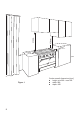
450 mm 650 mm 5 0 mm 5 0 0 mm Figure 1 8 Cooker overall dimensions [mm] ■■ height: min 900 - max 925 ■■ width: 900 ■■ depth: 600
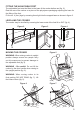
FITTING THE ADJUSTABLE FEET The adjustable feet must be fitted to the base of the cooker before use (fig. 2). Rest the rear of the cooker on a piece of the polystyrene packaging exposing the base for the fitting of the feet. Fit the no. 4 (four) legs by screwing them tight into the support base as shown in figure 3. LEVELLING THE COOKER The cooker may be levelled by screwing the lower ends of the feet IN or OUT (fig. 4).
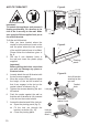
ANTI-TILT BRACKET Figure 8 900 mm 900 mm 450 Important! To restrain the appliance and prevent it tipping accidentally, fit a bracket to its rear to fix it securely to the wall. Make sure you also fit the supplied lock pin to the anti-tilt bracket. To fit the anti-tilt bracket: 1. 2. After you have located where the cooker is to be positioned, mark on the wall the place where the two screws of the anti-tilt bracket have to be fitted. Please follow the indications given in fig. 8.
ELECTRICAL REQUIREMENTS ■■ The appliance must be connected to the mains checking that the voltage corresponds to the value given in the rating plate and that the electrical cable sections can withstand the load specified on the plate. ■■ A suitable disconnection switch must be incorporated in the permanent wiring, mounted and positioned to comply with the local wiring rules and regulations.
LOCATING THE AREA FOR ELECTRICAL CONNECTION ELECTRIC CONNECTION Dotted line showing the position of the cooker when installed max 290 mm Area for ELECTRIC connection Figure 11 12
CONNECTION OF THE POWER SUPPLY CABLE Important! This cooker must be connected to the electricity supply only by an authorised person. To connect the feeder cable to the cooker it is necessary to: • Remove the two screws that hold shield “A” behind the cooker (fig. 12). • Open completely the cable clamp “D”. • Fitted with a 6-pole terminal block, position the U bolts onto terminal block ‘B’ (fig. 12) according to the diagrams in figs. 13 - 14. • Feed the supply cable through the cable clamp “D”.
Figure 12 Figure 13 230 V~ 230 V~, 240 V~ 1 2 3 4 5 B L1 N (L 2) PE D 230 V 3~ 230 V 3~, 240 V 3~ A 1 2 3 L1 4 5 1 N(L 2) PE 2 3 L1 230 V~ 230 V~, 240 V~ 4 L2 1 2 3 4 5 PE 3~ V 3~ 230 V 230 3~,V240 L 2 L 3 PE L1 5 L3 400 V 3N~ 400 V 3N~, 415 V 3N~ 1 2 3 4 5 1 2 3 4 5 N L2 L1 PE L1 L2 L3 N PE 400 V 415 2N~ V 2N~ 400 V 2N~, 400 V 2N~ 400 V 2N~, 415 V 2N~ 1 L1 2 L2 3 4 L3 1 2 3 4 5 5 N PE L1 Figure 14 14 400 V 3N~, 400 V415 3N~V 3N~ L2 N PE
1a 1 PR L/8 N/7 S1 P2 P1 P3 S V G C 3 4 1 2 5 F1 CF LF TL TM M S2 2 SH 1 S1 2 3 4 5 S2 2 SH P2 4 PILOT S1 P2 T 4a 2 SH P3 4 S2 4A S1 P2 CR 2 P2 F4 P1 2 4 F3 P1 2 4 F2 P1 P1 4 PILOT 4 S2 2 4 4a S H S2 4 4a F5 S1 P2 2 P4 P1 S2 2 SH S1 P2 2 F6 P1 P5 4 PILOT 4 ELECTRIC DIAGRAM Figure 15 15
ELECTRIC DIAGRAM KEY P1/2/5 Hob single zones elements P3 Hob double zone (oval) element P4 Hob double zone element F2/3/6 Energy regulators (single zones) F4/5 Energy regulators (double zones) F1 Oven switch TM Oven thermostat LF Oven lamp PR Oven programmer CF Cooling fan motor V Oven fan motor C Oven top element G Oven grill element S Oven bottom element TL Thermal overload S1 Thermostat pilot lamp S2 Hob elements pilot lamp CR Hob elements residual heat lamps M
CAUTION: ■■ ■■ ■■ ■■ ■■ ■■ USE AND CARE This appliance must be used only for the task it has explicitly been designed for, that is for domestic cooking of foodstuffs. Any other form of usage is to be considered as inappropriate and therefore dangerous. Do NOT place combustible materials or products on this appliance at any time. Do NOT use or store flammable materials in the appliance storage compartment or near this appliance. WARNING: Accessible parts will become Figure 16 hot when in use.
GREASE FILTER SEPARATELY) ■■ ■■ ■■ (OPTIONAL COMPONENT, CAN PURCHASED A special screen can be fitted at the back of the oven to catch grease particles, mainly when meat is being roasted. Slide in the grease filter on the back of the oven as in fig. 19. Clean the filter after any cooking! The grease filter can be removed for cleaning and should be washed regularly in hot soapy water. Always clean the filter after cooking as any solid residues on it might adversely affect the oven performance.
CONTROL PANEL Figure 20 10 8 7 9 6 5 4 3 2 1 Controls description 1. Front right cooking zone control knob 2. Rear right cooking zone control knob 3. Central cooking zone control knob 4. Rear left cooking zone control knob 5. Front left cooking zone control knob 6. Oven temperature control knob 7. Oven function selector control knob 8. Electronic programmer Pilot lamps: 9. Cooking zone/s ON indicator light 10.
OB VITROCERAMIC HOB Figure 21 4 2 3 1 5 6 VITROCERAMIC COOKING HOB 1. “Hi-Light” single zone, Ø 180 mm 1800 W 2. “Hi-Light” single zone, Ø 145 mm 1200 W 3. “Hi-Light” double zone (oval), Ø 145 x 250 mm 2000/1100 W 4. “Hi-Light” double zone, Ø 210/120 mm 2200/750 W 5. “Hi-Light” single zone, Ø 145 mm 1200 W 6. Cooking zones residual heat indicators Attention: Detach the appliance from the mains if the ceramic glass is cracked and contact the AfterSales Service.
HOW TO USE THE VITROCERAMIC HOB The ceramic surface of the hob allows a fast transmission of heat in the vertical direction, from the heating elements underneath the ceramic glass to the pans set on it. The heat does not spread in a horizontal direction, so that the glass stays “cool” at only a few centimeters from the cooking plate. The cooking zones are shown by painted disks on the ceramic surface. Before switching on the cooktop make sure that it is clean.
“Hi-light” double zoneS (figs. 25, 26) ■■ The heating element is formed of 2 coils of resistant material which reaches the working temperature quickly. ■■ This zone is controlled by a continuous energy regulator switch (fig. 24). The heat intensity can be regulated continuously from “0” to “12” (max). ■■ Check that the hob is clean and then switch on by turning the control knob. ■■ When the hob is working, the power on indicator light will be on.
SAFETY HINTS 1. Never put cooking foil or plastic materials on the ceramic surface when the hob is hot. 2. Make sure that the hob is clean before you use it. 3. Always ensure that the base of your saucepan is clean and dry before placing on the hob. 4. The glass-ceramic surface and pans must be clean. Carefully eliminate any food remains (especially containing sugar), dirt etc. with the aid of a cleansing agent. 5.
RESIDUAL HEAT INDICATORS The hob also features no. 6 (six) warning lights which are connected to the corresponding plates. When the temperature of a cooking plate is above 60°C, the relevant warning light will also light up to warn of heat on the surface of the hob. This light also stay on after the cooking plate has been switched off to show that the hob surface is still hot. This residual heat will lasts for a long time after the cooking plate has been switched off.
Elements usage table Figure 30 Knob setting COOKING HINTS: Temperature control knob 2 3 Warming 1 4 6 7 Cooking 5 8 10 11 12 Roasting - Frying 9 TYPE OF COOKING 0 Switched OFF 1 2 For melting operations (butter, chocolate). 2 3 4 To maintain food hot and to heat small quantities of liquid (sauces, eggs). 4 5 6 To heat bigger quantities; to whip creams and sauces (vegetables, fruits, soups). 6 7 Slow boiling, i.e.
COOKWARE: It is very important that the pans used on the hobs are made of a suitable material and have the correct base as follows: ■■ The base should be flat and smooth. ■■ Any rough part on the pan base could scratch the hob surface. ■■ Choose pans which are the same size as the hotplates and with bases that are as non reflective as possible. eg. dull and dark. Only pans recommended for use on ceramic hobs should be used.
COOKING WITH FAN ASSISTED OVEN Attention: The oven door becomes very hot during operation. Keep children away. GENERAL FEATURES This is an oven that presents particular features from an operational point of view. In fact, it is possible to insert 4 different programs to satisfy every cooking need, plus a defrost function using the fan only.
Figure 31 Figure 32 THERMOSTAT KNOB (fig. 32) To turn on the heating elements of the oven, set the function selector knob on the desired program and the thermostat knob onto the desired temperature. To set the temperature, it is necessary to make the knob indicator meet the chosen number. The elements will turn ON or OFF automatically according to the energy need which is determined by the thermostat.
CONVECTION COOKING WITH VENTILATION The upper and lower heating elements and the fan turn on. The heat coming from the top and bottom is diffused by forced convection. The temperature must be regulated between 50°C and the maximum temperature with the thermostat knob. Recommended for: For foods of large volume and quantity which require the same internal and external degree of cooking; for ie: rolled roasts, turkey, legs, cakes, etc.
COOKING ADVICE The external parts of the appliance become hot during operation. Keep children well out of reach. OVEN COOKING Before introducing the food, preheat the oven to the desired temperature. For a correct preheating operation, it is advisable to remove the tray from the oven and introduce it together with the food, when the oven has reached the desired temperature. Check the cooking time and turn off the oven 5 minutes before the theoretical time to recuperate the stored heat.
USE OF THE GRILL Preheat the oven for about 5 minutes. Introduce the food to be cooked, positioning the rack as close to the grill as possible. The dripping pan should be placed under the rack to catch the cooking juices and fats. Grilling with the oven door closed. Do not grill for longer than 30 minutes at any one time. ATTENTION: The oven door becomes very hot during operation. Keep children away.
RECOMMENDED COOKING TEMPERATURE Food °C °F Gas Mark Shelf Position* Cooking Time (approx) 190 375 5 2 or 3 20-25 mins CAKES Victoria sandwich Small cakes/buns 190 375 5 1 and 2 15-20 mins Maidera cake 180 350 4 2 or 3 20 mins Fruit cake 170 325 3 3 13/4 hours Rich fruit cake 150 300 2 3 or 4 21/2 hours Scones 225 425 8-9 2 8-10 mins Puff 225 425 8-9 2 10-20 mins Short crust 200 400 6 2 20-30 mins Plate tarts 200 - 210 400 - 410 6 1 or 2 30-35 mins Q
DIGITAL ELECTRONIC PROGRAMMER The electronic programmer is a device which groups together the following functions: ■■ 24 hours clock with illuminated display. ■■ Timer (up to 23 hours and 59 minutes). ■■ Program for automatic oven cooking. ■■ Program for semi-automatic oven cooking.
ELECTRONIC CLOCK (fig. 34) ELECTRONIC TIMER The programmer is equipped with an electronic clock with illuminated numbers which indicates hours and minutes. Upon immediate connection of the oven or after a power cut, three zeros will flash on the programmer display. To set the correct time of day it is necessary to push the button and then the or button until you have set the correct time (fig. 34). In another way push simultaneously the two buttons and at the same time push the or button.
AUTOMATIC OVEN COOKING To cook food automatically in the oven, it is necessary to: 1. Set the length of the cooking period. 2. Set the end of the cooking time. 3. Set the temperature and the oven cooking program. These operations are done in the following way: 1. 2. Set the length of the cooking period by button and the button pushing the to increase, or to decrease if you have passed the desired time (fig. symbol 37). The AUTO and the will illuminate.
SEMI-AUTOMATIC COOKING This is used to automatically switch off the oven after the desired cooking time has elapsed. There are two ways to set your oven: 1. Set the length of the cooking time by pushing the button and the button to advance, or to go backwards if you have passed the desired time (fig. 39). or 2. Set the end of the cooking time by pushing the button and the button to advance, or to go backwards if you have passed the desired time (fig. 40).
CLEANING AND MAINTENANCE GENERAL ADVICE ■■ ■■ ■■ ■■ ■■ ■■ ■■ Before you begin cleaning, you must ensure that the appliance is switched off and disconnected from the electrical power supply. It is advisable to clean when the appliance is cold and especially when cleaning the enamelled parts. Avoid leaving alkaline or acidic substances (lemon juice, vinegar, etc.) on the surfaces. Avoid using cleaning products with a chlorine or acidic base.
CLEANING THE CERAMIC HOB ■■ ■■ ■■ ■■ ■■ ■■ ■■ ■■ ■■ ■■ ■■ Figure 41 Remove spillages and other types of incrustations. Dust or food particles can be removed with a damp cloth. If you use a detergent, please make sure that it is not abrasive or scouring. Abrasive or scouring powders can damage the glass surface of the hob. All traces of the cleaner must be removed with a damp cloth. Dust, fat and liquids from food that has boiled over must be removed as soon as possible.
GRILL HEATING ELEMENT ■■ The heating element is self-cleaning and does not require maintenance. Figure 42 OVEN FLOOR The oven floor “F” (fig. 42) can be easily removed to facilitate cleaning. Remember to replace the floor correctly afterwards. Be careful not to confuse the tray “L” with the oven floor “F”. L F STORAGE COMPARTMENT The storage compartment is accessible through the pivoting panel (fig. 43). Figure 43 Do not store flammable material in the storage compartment.
STORAGE COMPARTMENT The storage compartment is accessible through the pivoting panel (fig. 45). Do not store flammable material in the storage compartment. Figure 45 REMOVING AND REPLACING THE INNER DOOR GLASS PANE FOR CLEANING If you wish to clean the inner glass of the door, make sure you follow the precautions and instructions very carefully. Replacing the glass pane incorrectly may result in damage to the appliance and may void your warranty.
REMOVING THE OVEN DOOR Figure 47a The oven door can easily be removed as follows: ■■ Open the door to the full extent (fig. 47a). ■■ Open the lever “A” completely on the left and right hinges (fig. 47b). ■■ Hold the door as shown in fig. 47d. ■■ Gently close the door (until left and right hinge levers “A” are hooked to part “B” of the door (figs. 47b, 47c). ■■ Withdraw the hinge hooks from their location following arrow “C” (fig. 47e). ■■ Rest the door on a soft surface.
REFIT THE DOOR ■■ Hold the door firmly (fig. 48a). ■■ Insert the hinge tongues into the slots, making sure that the groove drops into place as shown in the figure 48b. ■■ Open the door to its full extent. ■■ Fully close the levers “A” on the left and right hinges, as shown in the figure 48c. ■■ Close the door and check that it is properly in place.
Service and Maintenance SERVICING THE APPLIANCE Service may be obtained by contacting our Customer Service Centre to locate the nearest Authorised Delonghi Service Agent: Servicing shall be carried out only by authorized personnel. The appliance shall not be modified. TROUBLESHOOTING If you experience a problem with your oven, check the following points before calling our Customer Service Centre for assistance. 1. The power is switched on. 2. The controls are switched on. 3.
Desc ri ptio n s an d illu st r ations in this book let ar e gi v e n a s s i m p l y i n d i c a t i v e . The man u f actu rer res er ves the r ight, cons ider in g t h e c h a ra c t e r i s t i c s o f t h e model s described h e re, at any tim e and w ithout notic e , t o m a k e e v e n t u a l n e c e s s a r y modifi c atio n s fo r th e ir cons tr uction or for com m er c i a l n e e d s . w w w. de lo nghi. co m . au w w w.de lo nghi. co . nz Cod .