D E ’LON GHI COOKING INSTALLATION and SERVICE INSTRUCTIONS USE and CARE INSTRUCTIONS DEFP907W DEFP907S DUA L F U EL C OO K E R S distributed by DeLonghi Australia Pty Ltd DeLonghi New Zealand Ltd
Dear Customer, Thank you for having purchased and given your preference to our product. The safety precautions and recommendations reported below are for your own safety and that of others. They will also provide a means by which to make full use of the features offered by your appliance. Please keep this booklet in a safe place. It may be useful in future, either to yourself or to others in the event that doubts should arise relating to its operation.
IMPORTANT SAFETY PRECAUTIONS AND RECOMMENDATIONS IMPORTANT: This appliance is designed and manufactured solely for the cooking of domestic (household) food and is not suitable for any non domestic application and therefore should not be used in a commercial environment. The appliance guarantee will be void if the appliance is used within a non domestic environment i.e. a semi commercial, commercial or communal environment. Read the instructions carefully before installing and using the appliance.
■■ Do not use a steam cleaner because the moisture can get into the appliance thus make it unsafe. ■■ Do not touch the appliance with wet or damp hands (or feet). ■■ Do not use the appliance whilst in barefoot.
■■ WARNING: Unattended cooking on a hob with fat or oil can be dangerous and may result in fire. NEVER try to extinguish a fire with water, but switch off the appliance and then cover flame e.g. with a lid or a fire blanket. ■■ WARNING: Danger of fire: do not store items on the cooking surfaces. ■■ DO NOT USE OR STORE FLAMMABLE MATERIALS IN THE APPLIANCE STORAGE COMPARTMENT OR NEAR THIS APPLIANCE. ■■ DO NOT SPRAY AEROSOLS IN THE VICINITY OF THIS APPLIANCE WHILE IT IS IN OPERATION.
■■ Do not hang towels, dishcloths or other items on the appliance or its handle – as this could be a fire hazard. ■■ Clean the oven regularly and do not allow fat or oils to build up in the oven base or tray. Remove spillages as soon as they occur. ■■ Do not stand on the cooker or on the open oven door. ■■ Always stand back from the appliance when opening the oven door to allow steam and hot air to escape before removing the food.
INSTALLATION CAUTION: ■■ ■■ ■■ ■■ ■■ ■■ ■■ This appliance must be installed according to AS/NZS 5601.1 (latest edition). This appliance must be installed in accordance with these installation instructions. This appliance shall only be serviced by authorized personnel. This appliance is to be installed only by an authorised person in compliance with the current electrical regulations and in observation of the instructions supplied by the manufacturer.
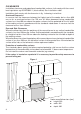
CLEARANCES Installation clearances and protection of combustible surfaces shall comply with the current local regulations eg. AS/NZS5601.1 (latest edition) Gas Installations code. Installation shall comply with the dimension in fig. 1a bearing in mind that. Overhead Clearances In no case shall the clearances between the highest part of the cooker be less than 650 mm or for an overhead exhaust fan 750 mm.
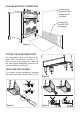
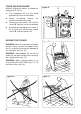
GAS AND ELECTRIC CONNECTION Dotted line showing the position of the cooker when installed max 273 mm Area for GAS and ELECTRIC connection Figure 2 FITTING THE ADJUSTABLE FEET The adjustable feet must be fitted to the base of the cooker before use (figs. 3 - 5). Rest the rear of the cooker on a piece of the polystyrene packaging exposing the base for the fitting of the feet. LEVELLING THE COOKER The cooker may be levelled by screwing the lower ends of the feet IN or OUT (fig. 5).
FIXING THE BACKGUARD Figure 6 Before installing the cooker, assemble the backguard “C” (fig. 6). ■■ The backguard “C” can be found packed at the rear of the cooker. ■■ Before assembling remove protective film/adhesive tape. ■■ Remove the two spacers “A” and the screw “B” from the rear of the cooktop. ■■ Assemble the backguard as shown in fig. 6 and fix it by screwing the central screw “B” and the spacers “A”.
Figure 8 ANTI-TILT BRACKET 900 mm 450 min 205 (*) max 210 (*) Important! To restrain the appliance and prevent it tipping accidentally, fit a bracket to its rear to fix it securely to the wall. Make sure you also fit the supplied lock pin to the anti-tilt bracket. 450 (*) depending on feet adjustment To fit the anti-tilt bracket: 1. After you have located where the cooker is to be positioned, mark on the wall the place where the two screws of the anti-tilt bracket have to be fitted.
GAS SUPPLY ■■ ■■ ■■ ■■ ■■ The connection must be performed by an authorised person according to the relevant standards. Before connecting the appliance to the gas main, mount the brass conical adaptor onto the gas inlet pipe, upon which the gasket has been placed (figs. 11a - 11b). Conical adaptor and gasket are supplied with the appliance (packed with conversion kit for use with Natural gas or ULPG).
Gas connection for NATURAL GAS Gas connection for ULPG Gas inlet pipe Gas inlet pipe Nipple Nipple Gasket Gasket Brass conical adaptor Brass conical adaptor Test point (Thread tight: use suitable seal) (Thread tight: use suitable seal) Test point adaptor Test point Gas regulator Figure 11a Figure 11b Chain security hole Figure 13 Plug Figure 12 13
2. Adjust the test point pressure or supply pressure to the value which is appropriate for the gas type. 3. The operation of the appliance must be tested when installation is completed. ■■ Turn on the appliance gas controls and light each burner individually and in combination. Check for a well defined blue flame without any yellow tipping. If any abnormality is evident then check that the burner cap is located properly and the injector nipple is aligned correctly.
Auxiliary and Semi-rapid burners Triple-ring burner J J Figure 14b Figure 14a Dual burner J Injector for inner crown J Injectors for outer crowns Figure 14c MINIMUM BURNER SETTING ADJUSTMENT Check whether the flame spreads to all burner ports when the burner is lit with the gas tap set to the minimum position. If some ports do not light, increase the minimum gas rate setting. Check whether the burner remains lit even when the gas tap is turned quickly from the maximum to the minimum position.
■■ Using a screwdriver turn the screw “F2” until the correct setting is obtained (fig. 15b). Outside crowns of DUAL burner: ■■ Light the DUAL burner. ■■ Set the gas valve to the “minimum rate” position of the inner + outer crowns. ■■ Remove the knob. ■■ Using a screwdriver turn the screw “F3” until the correct setting is obtained (fig. 15b). Normally for ULPG, the regulation screw is tightened up.
USE AND CARE CAUTION: ■■ ■■ ■■ ■■ ■■ ■■ This appliance must be used only for the task it has explicitly been designed for, that is for domestic cooking of foodstuffs. Any other form of usage is to be considered as inappropriate and therefore dangerous. Do NOT place combustible materials or products on this appliance at any time. Do NOT use or store flammable materials in the appliance storage compartment or near this appliance. WARNING: Accessible parts will become Figure 16 hot when in use.
GREASE FILTER SEPARATELY) ■■ ■■ ■■ (OPTIONAL COMPONENT, CAN BE PURCHASED A special screen can be fitted at the back of the oven to catch grease particles, mainly when meat is being roasted. Slide in the grease filter on the back of the oven as in fig. 19. Clean the filter after any cooking! The grease filter can be removed for cleaning and should be washed regularly in hot soapy water.
Figure 20 Left Right To remove the telescopic sliding shelf supports: ■■ Remove the side racks and the catalytic liners. ■■ Lay down the telescopic sliding shelf support and side racks, with the telescopic sliding shelf support underneath. ■■ Find the safety locks. These are the tabs that clip over the wire of the side rack (arrow 1 in fig. 21). ■■ Pull the safety locks away from the wire to release the wire (arrow 2 in fig. 21).
CONTROL PANEL Figure 22 9 8 7 6 5 4 3 2 1 Controls description 1. Front right burner control knob 2. Rear right burner control knob 3. Central burner control knob 4. Rear left burner control knob 5. Front left burner control knob 6. Oven temperature control knob 7. Oven function selector control knob 8. Electronic programmer Pilot lamp 9.
GAS HOB Figure 23 2 2 4 1 3 GAS BURNERS 1. Auxiliary burner (A) Natural Gas MJ/h ULPG MJ/h 3.60 3.60 2. Semi-rapid burner (SR) 6.30 6.30 3. Triple-ring burner (TR) 12.70 11.90 3.60 (*) 16.00 (**) 3.20 (*) 13.00 (**) 4. Dual burner (D) (*) Power calculated with only inner crown operating. (**) Power calculated with inner and outer crowns operating. Notes: ■■ The electric ignition is incorporated in the knobs.
GAS BURNERS (Auxiliary, Semi-rapid and Triple ring) Gas flow to the burners is adjusted by turning the knobs (illustrated in fig. 24) which control the valves.
LIGHTING GAS BURNERS FITTED WITH FLAME FAILURE SAFETY DEVICE AND ELECTRONIC IGNITION (Auxiliary, Semi-rapid and Triple ring) 1. Check that the electricity is switched on to allow spark ignition. 2. The gas flow to the burner is controlled by taps with safety cut-out device. If the burner flame should go out, the safety cut-off valve will automatically stop the gas flow. The switch for the electric ignition is incorporated in the knobs. 3.
GAS BURNERS (Dual) The Dual burner is a very flexible burner which allows different regulations and optimal cooking. It is composed by one inner and one outer crown; the flame of the inner crown can be regulated separately from the flame of the outer crown. The Dual Burner can be used: • as a small burner (flame produced only by the inner crown) which can be adjusted from the maximum ( ) to the minimum ( ) position.
■■ Note that, if you are using a burner at the minimum setting, you turn the knob clockwise past the maximum setting before reaching the “0” (off) position. ■■ To switch off, turn the knob clockwise until you hear the safety click (“0” off position). Note: When the range is not being used, set the gas knobs to their closed position and also close the gas shut-off valve placed on the main gas supply line. Caution! The range becomes very hot during operation. Keep children well out of reach.
CHOICE OF BURNER The burner must be chosen according to the diameter of the pans and energy required. For optimum efficiency uso a wok or pan no smaller than 230 mm diameter.
CORRECT USE OF THE DUAL AND TRIPLE-RING BURNER (figs. 30, 31) ■■ The flat-bottomed pans are to be placed directly onto the pan-support. ■■ To use the WOK, you must place the wok stand in the CORRECT position as shown in figs. 30 - 31. IMPORTANT The special grille for wok pans (fig. 31) MUST BE PLACED ONLY over the pan-rest for the dual or triple-ring burner.
COOKING WITH MULTIFUNCTION OVEN OPERATING PRINCIPLES Attention: The oven door becomes very hot during operation. Keep children away. GENERAL FEATURES As its name indicates, this is an oven that presents particular features from an operational point of view. In fact, it is possible to insert 7 different programs to satisfy every cooking need. The 7 positions, thermostatically controlled, are obtained by 4 heating elements which are: ■■ Bottom element 1725 W (@230 V) 1878 W (@240 V) ■■ Grill element a.
Figure 32 Figure 33 MULTIFUNCTION THERMOSTAT KNOB (fig. 33) To turn on the heating elements of the oven, set the function selector knob on the desired program and the thermostat knob onto the desired temperature. To set the temperature, it is necessary to make the knob indicator meet the chosen number. The elements will turn ON or OFF automatically according to the energy need which is determined by the thermostat.
GRILLING The infra-red heating element is switched on. The heat is diffused by radiation. Use with the oven door closed and the thermostat knob must be regulated between 50°C and 225°C maximum. For correct use see chapter “USE OF THE GRILL”. Note: It is recommended that you do not grill for longer than 30 minutes at any one time. Attention: The oven door becomes very hot during operation. Keep children away.
MAINTAINING TEMPERATURE AFTER COOKING OR SLOWLY HEATING FOODS The upper element and the circular element connected in series, are switched on; also the fan is on. The heat is diffused by forced convection with the most heat being produced by the upper element. The temperature must be regulated between 50°C and 140°C with the thermostat knob. Recommended for: To keep foods hot after cooking. To slowly heat already cooked foods.
SIMULTANEOUS COOKING DIFFERENT FOODS OF The MULTIFUNCTION oven set on position or gives simultaneous heterogeneous cooking of different foods. Different foods such as fish, cake and meat can be cooked together without mixing the smells and flavours. This is possible since the fats and vapors are oxidized while passing through the electrical element and therefore are not deposited onto the foods.
RECOMMENDED COOKING TEMPERATURE °C °F Gas Mark Shelf Position* Cooking Time (approx) Victoria sandwich 190 375 5 2 or 3 20-25 mins Food CAKES Small cakes/buns 190 375 5 1 and 2 15-20 mins Maidera cake 180 350 4 2 or 3 20 mins Fruit cake 170 325 3 3 13/4 hours Rich fruit cake 150 300 2 3 or 4 21/2 hours Scones 225 425 8-9 2 8-10 mins Puff 225 425 8-9 2 10-20 mins Short crust 200 400 6 2 20-30 mins Plate tarts 200 - 210 400 - 410 6 1 or 2 30-35 mins Q
DIGITAL ELECTRONIC PROGRAMMER The electronic programmer is a device which groups together the following functions: ■■ 24 hours clock with illuminated display. ■■ Timer (up to 23 hours and 59 minutes). ■■ Program for automatic oven cooking. ■■ Program for semi-automatic oven cooking.
ELECTRONIC CLOCK (fig. 35) ELECTRONIC TIMER The programmer is equipped with an electronic clock with illuminated numbers which indicates hours and minutes. Upon immediate connection of the oven or after a power cut, three zeros will flash on the programmer display. To set the correct time of day it is necessary button and then the or to push the button until you have set the correct time (fig. 35). In another way push simultaneously the two buttons and at the same time or button.
AUTOMATIC OVEN COOKING To cook food automatically in the oven, it is necessary to: 1. 2. 3. Set the length of the cooking period. Set the end of the cooking time. Set the temperature and the oven cooking program. These operations are done in the following way: 1. 2. Set the length of the cooking period button and the by pushing the button to increase, or to decrease if you have passed the desired time (fig. symbol 38). The ‘AUTO’ and the will illuminate.
SEMI-AUTOMATIC COOKING This is used to automatically switch off the oven after the desired cooking time has elapsed. There are two ways to set your oven: 1. Set the length of the cooking time button and the by pushing the button to advance, or to go backwards if you have passed the desired time (fig. 40). or 2. Set the end of the cooking time by pushing the button and the button to advance, or to go backwards if you have passed the desired time (fig. 41).
CLEANING AND MAINTENANCE Maintenance Period Description Daily ■■ Clean gas cooktop as per instructions below ■■ Remove burner caps, burner rings & base and clean using non abrasive detergent & rinse in cold water & dry thoroughly before replacing back on hob ■■ Clean ignitor tip & thermocouple using damp soapy cloth and dry thoroughly ■■ Contact your local authorized gas Service Agent to perform a thorough check on all gas components on the gas cooker Monthly 3 - 4 Yearly GENERAL ADVICE ■■ ■■ ■
INSIDE OF OVEN The oven should always be cleaned after use when it has cooled down. The cavity should be cleaned using a mild detergent solution and warm water. Suitable proprietary chemical cleaners may be used after first consulting with the manufacturers recommendations and testing a small sample of the oven cavity. Abrasive cleaning agents or scouring pads/cloths should not be used on the cavity surface.
BURNERS ■■ They can be removed and washed only with soapy water. Detergents can be used but must not be abrasive or corrosive. Do not use abrasive sponges or pads. Do not put in dishwasher. ■■ After each cleaning, make sure that the burner-caps, as well as the burners, have been well wiped off and CORRECTLY POSITIONED. ■■ Check that the electrode “S” (figs. 42a, 43a, 44a) next to each burner is always clean to ensure trouble-free sparking. ■■ Check that the probe “T” (figs.
Figure 42a Figure 42b Figure 44a C S T F Figure 44b T S Figure 44c Figure 43a Figure 43c T S Figure 43b A Figure 44d B 41
REPLACING THE OVEN LIGHT WARNING: Ensure the appliance is switched off before replacing the lamp to avoid the possibility of Figure 45 electric shock. ■■ Let the oven cavity and the heating elements to cool down. B A ■■ Disconnect the appliance from the electrical power supply. ■■ Remove the protective cover “A” (fig. 45).
Figure 48a REMOVING THE OVEN DOOR The oven door can easily be removed as follows: ■■ Open the door to the full extent (fig. 48a). ■■ Open the lever “A” completely on the left and right hinges (fig. 48b). ■■ Hold the door as shown in fig. 48d. ■■ Gently close the door (until left and right hinge levers “A” are hooked to part “B” of the door (figs. 48b, 48c). ■■ Withdraw the hinge hooks from their location following arrow “C” (fig. 48e). ■■ Rest the door on a soft surface.
REFIT THE DOOR 1. Hold the door firmly (fig. 49a). 2. Insert the hinge tongues into the slots, making sure that the groove drops into place as shown in the figure 49b. 3. Open the door to its full extent. 4. Fully close the levers “A” on the left and right hinges, as shown in the figure 49c. 5. Close the door and check that it is properly in place.
Cleaning the Panes of Glass Figure 50a The oven door is fitted with no. 2 panes: ■■ no. 1 outside; ■■ no. 1 inner. To clean the panes on both sides it is necessary to remove the inner pane as follows. Removing the Inner Pane of Glass 1. Lock the door open: ■■ Open the door to the full extent (fig. 48a, 50a). ■■ Open the lever “A” completely on the left and right hinges (fig. 48b). ■■ Hold the door as shown in fig. 48d.
Figure 50c AFTER CLEANING, REPLACE THE INNER GLASS PANE When replacing the inner glass pane, make sure that: ■■ D You replace the pane correctly, as shown. The pane must be in the position described below in order to fit into the door and to ensure that the oven operates safely and correctly. To reassemble the inner pane of the oven door operate as follows: 1. Make sure the door is locked open (see fig. 48c). 2. Replace the inner pane: ■■ Check that the four rubber pads are in place (“D” in fig.
SERVICE AND MAINTENANCE If the ignition spark fails to ignite or does not light the gas, check the following items before calling our Customer Service Centre to obtain the nearest Authorised Service Agent: ■■ Burner is reassembled and located correctly. ■■ Spark electrode and white ceramic are clean and dry. ■■ 240 VAC power supply is connected. Contact the local gas utility or our Customer Service Centre to obtain the nearest Authorized Service Agent.
TM 48 V S G C LF 1 2 3 4 5 6 7 8 9 10 11 CF CIR 6a 7a 8a 9a 10a 11a 1a 2a 3a 4a 5a F1 S1 TL M L N 1 1a T PR L/8 N/7 PA A ELECTRIC DIAGRAM Figure 51
ELECTRIC DIAGRAM KEY F1 Oven switch TM Oven thermostat LF Oven lamp CF Cooling fan motor PR Oven programmer C Oven top heating element G Oven grill heating element V Oven fan motor S Oven bottom heating element CIR Oven circular heating element PA Ignition switches group A Ignition coil TL Thermal overload S1 Thermostat pilot lamp M Terminal block T Earth connection 49
Desc ri ptio n s an d illu st r ations in this book let ar e gi v e n a s s i m p l y i n d i c a t i v e . The man u f actu rer res er ves the r ight, cons ider in g t h e c h a ra c t e r i s t i c s o f t h e model s described h e re, at any tim e and w ithout notic e , t o m a k e e v e n t u a l n e c e s s a r y modifi c atio n s fo r th e ir cons tr uction or for com m er c i a l n e e d s . w w w. de lo nghi. co m . au w w w.de lo nghi. co . nz Cod .