IN STALLATI ON a n d S E RV I C E INST RUCT IONS US E a n d C A R E I N S T R UCT IONS BUILT-IN GAS ON GLASS HOBS Models: DEGH60BG - DEGH70BG - DEGH90BG distributed by DèLonghi Pty Ltd
Dear Customer, Thank you for having purchased and given your preference to our product. The safety precautions and recommendations reported below are for your own safety and that of others. They will also provide a means by which to make full use of the features offered by your appliance. Please keep this booklet in a safe place. It may be useful in future, either to yourself or to others in the event that doubts should arise relating to its operation.
IMPORTANT PRECAUTIONS AND RECOMMENDATIONS FOR USE OF ELECTRICAL APPLIANCES Use of any electrical appliance implies the necessity to follow a series of fundamental rules. In particular: ■■ Never touch the appliance with wet hands or feet. ■■ Do not operate the appliance barefooted. ■■ The appliance is not intended for use by young children or infirm persons without supervision. ■■ Young children should be supervised to ensure they do not play with the appliance.
INSTALLATION CAUTION: ■■ ■■ ■■ ■■ ■■ ■■ This appliance must be installed in accordance with these installation instructions, local gas fitting regulations, municipal building codes, water supply regulations, electrical wiring regulations, - Gas Installations and ony other relevant statutory regulations. This appliance shall be only be serviced by authorized personnel. This appliance is to be installed only by an authorised person.
N.B. The connection of the appliance to earth is mandatory. If the installation requires alterations to the domestic electrical system call a qualified electrician. He should also check that the socket cable section is suitable for the power drawn by the appliance. Replacing the power cord must be done by a qualified electrician in accordance with the instructions supplied by the manufacturer and in compliance with established electrical regulations.
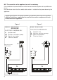
CLEARANCES Installation clearances and protection of combustible surfaces shall comply with the current local regulations e.g. AS/NZS5601 - Gas Installations code. M o d el : DE G H 6 0 B G Model: D E GH 70B G 585 715 10 5 (2 60 54 (1) 48 0 48 0 54 (1) 60 (2 )( )( 3) 5 3) 10 560 560 Figure 3b Figure 3a Mo d e l: D EGH 9 0 B G 869 0 48 0 60 (2 54 (1) )( 3) 51 840 Figure 3c (1) 54 mm from top of countertop.
650 mm 450 mm M o d el : DE GH 6 0 B G 500 m m 212,5 mm minimum between the side of the cut-out and the side wall A M odel: D E GH 70B G 650 mm 450 mm Figure 4a 500 m m 260 mm minimum between the side of the cut-out and the side wall B A. 212.5 mm minimum between the side of the cut-out and the side wall. B. 260 mm minimum between the side of the cut-out and the side wall. C. 214.5 mm minimum between the side of the cut-out and the side wall.
The installation shall comply with the dimensions in Figures 3a, 3b or 3c and 4a, 4b or 4c, bearing in mind that: ■■ A partition between the base of the hob and the cupboard below should be fitted 30 mm below the workbench surface if the cupboard is to be used for storage. ■■ If the hob is installed over a built-in oven, the oven shall be provided with cooling fan motor. The two appliances shall be connected to the gas/electrical supply with independent connections.
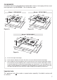
FASTENING THE COOKTOP Each cooktop is provided with an installation kit including brackets and screws for fastening the cooktop to benches from 30 to 40mm thick. The kit includes two “F” type brackets (for the front of the cooktop), two “R” type brackets (for the rear of the cooktop) and four self-threading screws “S” (figs. 7a and 7b). –– Cut the unit according to the dimensions in fig. 3a or 3b. –– Turn the hob upside down and rest the glass side on a soft surface.
GAS SUPPLY ■■ This appliance is suitable for use with Natural Gas or ULPG (Check the “gas type” sticker attached to the appliance). ■■ For Natural Gas the gas supply must be regulated to obtain a pressure of 1 kPa with the two semi-rapid (SR) burners operating at the maximum. ■■ For ULPG models connect the gas supply directly to the appliance test point adaptor (supplied with the conversion kit) and ensure that the supply pressure is regulated to 2.75 kPa.
5. Check the minimum burner setting by quickly rotating the gas control knob from the maximum to the minimum position, the flame must not go out. If adjustment is required carry out the “minimum burner setting adjustment” procedure described below. 6.
TABLE FOR THE CHOICE OF THE INJECTORS Natural Gas ULPG 1.0 2.75 Test Point Pressure [kPa] Injector Orifice Dia. [mm] Gas Consumption [MJ/h] Injector Orifice Dia. [mm] Gas Consumption [MJ/h] Auxiliary (AUX) 0.85 3.60 0.53 3.60 Semi-rapid (SR) 1.12 6.30 0.70 6.30 Rapid (R) 1.45 10.40 0.91 10.80 Triple-ring (TR) (*) 1.60 12.70 0.95 11.
CONVERSION PROCEDURE (to convert to Natural gas or to ULPG) REPLACING THE INJECTORS The conversion procedure must be carried out only by an authorised person. This appliance is suitable for use with Natural gas or Universal LPG (check the “gas type” sticker attached to the appliance). The nominal gas consumption and injector size details are provided in table at page 13. To replace the injectors proceed as follows: ■■ Remove pan supports and burners from the cooktop.
MINIMUM BURNER SETTING ADJUSTMENT Check whether the flame spreads to all burner ports when the burner is lit with the gas tap set to the minimum position. If some ports do not light, increase the minimum gas rate setting. Check whether the burner remains lit even when the gas tap is turned quickly from the maximum to the minimum position. If the burner does not remain lit, increase the minimum gas rate setting. The procedure for adjusting the minimum gas rate setting is described below.
USE and CARE CAUTION: ■■ This appliance must be used only for the task it has explicitly been designed for, that is for domestic cooking of foodstuffs. Any other form of usage is to be considered as inappropriate and therefore dangerous. Do not use this appliance as a space heater. ■■ Do NOT place combustible materials or products on this appliance at any time. Do NOT use or store flammable materials near this appliance. ■■ Do NOT spray aerosols in the vicinity of this appliance while it is in use.
Mo d e l: D EGH 7 0 B G 2 2 3 2 1 4 3 Figure 12b 9 8 7 6 5 Mo d e l: D EGH 9 0 B G 2 2 2 4 1 3 1 Figure 12c 5 9 8 6 7 GAS BURNERS CONTROL KNOBS 1. Auxiliary (AUX) 3.60 MJ/h 5. Burner 1 (Auxiliary) 2. Semi-rapid (SR) 6.30 MJ/h 6. Burner 2 (right Semi-rapid) 3. Rapid (R) 10.40 MJ/h (NG) 10.80 MJ/h (ULPG) 7. Burner 4 (Triple-ring) 8. Burner 2 (left Semi-rapid) 4. Triple ring (TR) 12.70 MJ/h (NG) 11.90 MJ/h (ULPG) 9. Burner 3 (Rapid) 10.
USING GAS BURNERS ■■ Check that the electricity is switched on to allow spark ignition. ■■ Make sure that all controls are turned to zero. ■■ The gas flow to the burner is controlled by a tap incorporating a safety cut-off valve. If the burner flame should go out for some reason, the safety valve will automatically stop the gas flow. The switch of the electric ignition is incorporated in the knobs.
LIGHTING GAS BURNERS FITTED WITH FLAME FAILURE SAFETY DEVICE In order to light the burner, you must: 1. Turn the knob (figs. 13a - 13b) in anti-clockwise direction up to the maximum aperture (symbol ), push in and hold the knob; this will light the gas. If there is no mains electrical supply, bring a lighted match close to the burner. 2. Wait for about ten seconds after the gas burner has been lit before letting go of the knob (valve activation delay). 3.
CORRECT USE OF TRIPLE-RING BURNER (ONLY FOR THE MODELS DEGH70BG, DEGH90BG) ■■ The flat-bottomed pans are to be placed directly onto the pan-support. ■■ To use the WOK, you must place the wok stand in the CORRECT position as shown in fig. 15b. IMPORTANT: The special grille for wok pans (fig. 15b) MUST BE PLACED ONLY over the pan-rest for the triple-ring burner.
Do not place anything, e.g. flame tamer, asbestos mat, between pan and pan support as serious damage to the appliance may result. Do not remove the pan support and enclose the burner with a wok stand as this will concentrate and deflect heat onto the hotplate. Do not use large pots or heavy weights which can bend the pan support or deflect flame onto the hotplate. Locate pan centrally over the burner so that it is stable and does not overhang the appliance.
CLEANING and MAINTENANCE GENERAL ADVICE ■■ ■■ ■■ ■■ ■■ ■■ Before you begin cleaning you must ensure that the hob is switched off. It is advisable to clean when the appliance is cold and especially when cleaning the enamelled parts. All enamelled surfaces have to be washed with soapy water or some other non-abrasive product with a sponge and are to be dried preferably with a soft cloth. Avoid leaving alkaline or acid substances (lemon juice, vinegar etc.) on the surfaces.
BURNERS AND GRIDS ■■ These parts can be removed and cleaned with appropriate products. ■■ After cleaning, the burners and their flame spreaders must be well dried and correctly replaced. ■■ It is very important to check that the burner flame spreader and the cap have been correctly positioned. Failure to do so can cause serious problems. ■■ Check that the electrode “S” (figs. 18 - 21) next to each burner is always clean to ensure trouble-free sparking. ■■ Check that the probe “T” (figs.
CORRECT POSITIONING OF THE AUXILIARY, SEMI-RAPID AND RAPID BURNERS Figure 19 It is very important to check that the burner flame spreader “F” and the cap “C” have been correctly positioned (see figs. 18 and 19). ■■ They shall be level and must not rotate. ■■ Failure to do so can cause serious problems. The pan supports shall be correctly positioned as indicated in fig. 20. ■■ The pan supports shall be level and must not rotate.
CORRECT POSITIONING OF THE TRIPLE RING BURNER (ONLY FOR THE MODELS DEGH70BG, DEGH90BG) Figure 23 The triple ring burner must be correctly positioned (see figs. 21, 22 and 23). ■■ The burner ribs must be fitted in their housing as shown by the arrow. ■■ The burner correctly positioned must not rotate. ■■ Then position the cap “A” and the ring “B”. They shall be level. The pan support shall be correctly positioned as indicated in fig. 24. ■■ The pan support shall be level and must not rotate.
SERVICE AND MAINTENANCE If the ignition spark fails to ignite or does not light the gas, check the following items before calling our Customer Service Centre to obtain the nearest Authorised Delonghi Service Agent: ■■ Burner is reassembled and located correctly. ■■ Spark electrode and white ceramic are clean and dry. ■■ 230 or 240 VAC power supply is connected. Contact the local gas utility or our Customer Service Centre to obtain the nearest Authorized Delonghi Service Agent.
Descriptions and illustrations in this booklet are given as simply indicative. The manufacturer reserves the right, considering the characteristics of the models described here, at any time and without notice, to make eventual necessary modifications for their construction or for commercial needs.
Cod.