D E ’LON GHI COOKING INSTALLATION and SERVICE INSTRUCTIONS USE and CARE INSTRUCTIONS DEGHSL60 DEGHSL75 DEGHSL90 GAS COOKTOPS distributed by DeLonghi Australia Pty Ltd DeLonghi New Zealand Ltd
Dear Customer, Thank you for having purchased and given your preference to our product. The safety precautions and recommendations reported below are for your own safety and that of others. They will also provide a means by which to make full use of the features offered by your appliance. Please keep this booklet in a safe place. It may be useful in future, either to yourself or to others in the event that doubts should arise relating to its operation.
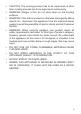
IMPORTANT SAFETY PRECAUTIONS AND RECOMMENDATIONS IMPORTANT: This appliance is designed and manufactured solely for the cooking of domestic (household) food and is not suitable for any non domestic application and therefore should not be used in a commercial environment. The appliance guarantee will be void if the appliance is used within a non domestic environment i.e. a semi commercial, commercial or communal environment. Read the instructions carefully before installing and using the appliance.
• • • • • • • • • • • 4 Do not touch the appliance with wet or damp hands (or feet). Do not use the appliance whilst in barefoot.
• • • • • • • • CAUTION: The cooking process has to be supervised. A short term cooking process has to be supervised continuously. WARNING: Danger of fire: do not store items on the cooking surfaces. WARNING: If the hob is cracked or otherwise damaged by falling objects etc., disconnect the appliance from the electrical power supply to avoid the possibility of electric shock and call Customer Service.
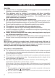
INSTALLATION CAUTION: ■■ Important: The use of suitable protective clothing/gloves is recommended when handling or cleaning of this appliance. ■■ This appliance must be installed in accordance with these installation instructions, local gas fitting regulations, municipal building codes, water supply regulations, electrical wiring regulations, - Gas Installations and ony other relevant statutory regulations. ■■ The appliance must be housed in heat-resistant units.
■■ ■■ ■■ ■■ 3. The wire which is coloured brown must be connected to the terminal marked “L” (Live) or “A” (Active) or coloured Red. A suitable isolating switch providing full disconnection from the mains power supply (under overvoltage category III conditions) shall be incorporated in the permanent wiring, mounted and positioned to comply with the local wiring rules and regulations.
CLEARANCES Installation clearances and protection of combustible surfaces shall comply with the current local regulations e.g. AS/NZS5601 - Gas Installations code. Figure 2a A B F C E G 650 mm 450 mm D The thermal protection barrier must be: • removable with the use of a tool for installation and service; • heat-resistant; • made from low thermal conductivity material.
(*) From top of countertop (**) Between the back edge of the cut-out and the back of the countertop. (***) From the side edge of the cut-out to any vertical combustible surface. If this distance is less than 200 mm, the surface shall be protected (in accordance with AS/NZS5601) to a height of not less than 150 mm above the hob for the full dimension (width or depth) of the cooking surface area.
FASTENING THE COOKTOP Each cooktop is provided with an installation kit including brackets and screws for fastening the cooktop to benches from 30 to 40mm thick. Models DEGHSL60, DEGHSL75 (fig. 3a): The kit includes two “F” type brackets (for the front of the cooktop), two “R” type brackets (for the rear of the cooktop) and four selfthreading screws “S”. Model DEGHSL90 (fig.
GAS SUPPLY ■■ ■■ ■■ For Natural Gas the gas supply must be regulated to obtain a pressure of 1 kPa: –– with the two semi-rapid (SR) burners operating at the maximum - model DEGHSL60 only; –– with the triple-ring (TR) burner operating at the maximum - model DEGHSL75 only; –– with the dual (DB) burner operating at the maximum (inside and outside flames in simultaneously at the maximum) - model DEGHSL90 only.
tighten or replace connections as appropriate. Warning: Do not use any naked flame to check for leaks. 2. The operation of the appliance MUST be tested before leaving. 3. Adjust the test point pressure or supply pressure to the value which is appropriate for the gas type. 4. Turn on the appliance gas controls and light each burner. Check for a well defined blue flame without any yellow tipping.
TABLE FOR THE CHOICE OF THE INJECTORS Natural Gas ULPG 1.0 2.75 Test Point Pressure [kPa] Injector Orifice Dia. [mm] Gas Consumption [MJ/h] Injector Orifice Dia. [mm] Gas Consumption [MJ/h] Auxiliary (AUX) 0.92 3.90 0.56 3.90 BURNER Semi-rapid (SR) 1.17 6.50 0.70 6.20 Rapid (R) (1) 1.54 11.75 0.98 11.75 Triple-ring compact (TRC) (2) 1.48 10.70 0.88 9.60 Triple-ring (TR) (3) 1.68 13.70 1.04 14.10 Dual (DB) - inner crown (4) 0.72 2.40 0.43 2.
and replace with test point adaptor (see figs. 4a, 4b). ■■ If the cooktop is suitable for use with Universal LPG and must be converted for use with Natural gas, before connecting to the gas main remove the appliance test point adaptor and replace with gas regulator (see figs. 4a, 4b). Auxiliary, semi-rapid and rapid burner (rapid only for the models DEGHSL75, J DEGHSL90) NOTE: Gas regulator and test point adaptor are supplied with the appliance (packed with conversion kit).
MINIMUM BURNER SETTING ADJUSTMENT Check whether the flame spreads to all burner ports when the burner is lit with the gas tap set to the minimum position. If some ports do not light, increase the minimum gas rate setting. Check whether the burner remains lit even when the gas tap is turned quickly from the maximum to the minimum position. If the burner does not remain lit, increase the minimum gas rate setting. The procedure for adjusting the minimum gas rate setting is described below.
USE and CARE CAUTION: ■■ This appliance must be used only for the task it has explicitly been designed for, that is for domestic cooking of foodstuffs. Any other form of usage is to be considered as inappropriate and therefore dangerous. Do not use this appliance as a space heater. ■■ Do NOT place combustible materials or products on this appliance at any time. Do NOT use or store flammable materials near this appliance. ■■ Do NOT spray aerosols in the vicinity of this appliance while it is in use.
M o d e l: DEGHSL90 2 3 7 1 4 Figure 7c 15 14 8 9 10 11 GAS BURNERS 1. 2. 3. 4. 5. 6. 7. Auxiliary (A) Semi-rapid (SR) Semi-rapid (SR) Rapid (R) Triple-ring compact (TRC) Triple-ring (TR) Dual (DB) (*) (*) IMPORTANT: The Dual burner (model DEGHSL90 only) is controlled by two separate knobs; one knob for the inner crown only and one knob for the outer crown only. The inner and outer crown can be used together or separately.
USING GAS BURNERS ■■ Check that the electricity is switched on to allow spark ignition. ” (burner off). ■■ Make sure that all controls are turned to “ ■■ The gas flow to the burner is controlled by a tap incorporating a safety cut-off valve. If the burner flame should go out for some reason, the safety valve will automatically stop the gas flow. The switch of the electric ignition is incorporated in the knobs.
LIGHTING GAS BURNERS FITTED WITH FLAME FAILURE SAFETY DEVICE In order to light the burner, you must: 1. Turn the knob (figs. 8a - 8b) in anti-clockwise direction up to the maximum aperture (symbol “ ” ), push in and hold the knob; this will light the gas. If there is no mains electrical supply, bring a lighted match close to the burner. 2. Wait for about ten seconds after the gas burner has been lit before letting go of the knob (valve activation delay). 3.
DUAL BURNER OPERATION/CONTROL KNOBS MODEL DEGHSL90 ONLY 1 1 2 2 1+2 IMPORTANT: After using the dual burner check both the control knobs are in the closed “ ” position.
COOKING HINTS FOR GAS HOBS ■■ The burner must be chosen according to the diameter of the pans and energy required. ■■ The largest can be used for boiling, to seal meat or foods that are cooked quickly, and the smallest for stews and sauces. ■■ Always ensure that you use the correct size of saucepan. ■■ For fast boiling, make sure the flame just reaches the edge of the pan. Flames going up the side of the pan means wasted heat and the contents of the pan will take longer to boil.
SMALL PAN ADAPTER - MODEL DEGHSL90 ONLY This adapter is to be placed: ■■ on top of the Dual burner (used with the inner crown only) when using small diameter pans, in order to prevent them from tipping over. IMPORTANT: To avoid any burner malfunction: ■■ this adapter MUST be placed correctly (figs.
WOK STAND (figs. 12a - 12b, 13a - 13b, 14a - 14b) This special grille for woks should be placed over the pan-rest for the triple-ring compact, triple ring or Dual burner (depending on models). Warning: ■■ The flat-bottomed pans are to be placed directly onto the pan-support. ■■ To use the WOK, you must place the wok stand in the CORRECT position as shown.
Model: DEGHSL75 (with triple-ring burner) WRONG CORRECT Figure 13a Figure 13b Model: DEGHSL90 (with dual burner) WRONG CORRECT Figure 14a 24 Figure 14b
CLEANING and MAINTENANCE GENERAL ADVICE ■■ ■■ ■■ ■■ ■■ ■■ ■■ ■■ Before you begin cleaning, you must ensure that the appliance is switched off and disconnected from the electrical power supply. Important: The use of suitable protective clothing/gloves is recommended when handling or cleaning of this appliance. Under no circumstances should any external covers be removed for servicing or maintenance except by suitable qualified personnel.
BURNERS ■■ ■■ ■■ ■■ ■■ ■■ These parts can be removed and cleaned with appropriate products. After cleaning, the burners and their flame spreaders must be well dried and correctly replaced. Check that the electrode/s “S” (figs. 15a, 15c, 15d, 15e) next to each burner is/are always clean to ensure trouble-free sparking. Check that the probe/s “T” (figs. 15a, 15c, 15d, 15e) next to each burner is/are always clean to ensure correct operation of the safety valves.
TRIPLE-RING COMPACT BURNER (Model: DEGHSL60) TRIPLE-RING BURNER (Model:DEGHSL75) F2 F1 S T S T Figure 15c Figure 15d DUAL BURNER (Model: DEGHSL90) F3 T S T Figure 15e S A B Figure 15f Figure 15g 27
PAN SUPPORTS ■■ ■■ ■■ ■■ ■■ These parts can be removed and cleaned with appropriate products. After cleaning, they must be well dried and correctly replaced. It is very important to check that the pan supports have been correctly positioned. Failure to do so can cause serious problems. The prongs of the pan supports must always be centred with the burners (fig. 16a). The raised portion of the pan supports shall NOT face the sides of the cooktop (fig. 16b).
SERVICE AND MAINTENANCE If the ignition spark fails to ignite or does not light the gas, check the following items before calling our Customer Service Centre to obtain the nearest Authorised Delonghi Service Agent: ■■ Burner is reassembled and located correctly. ■■ Spark electrode and white ceramic are clean and dry. ■■ 230 or 240 VAC power supply is connected. Contact the local gas utility or our Customer Service Centre to obtain the nearest Authorized Delonghi Service Agent.
Desc ri ptio n s an d illu st r ations in this book let ar e gi v e n a s s i m p l y i n d i c a t i v e . The man u f actu rer res er ves the r ight, cons ider in g t h e c h a ra c t e r i s t i c s o f t h e model s described h e re, at any tim e and w ithout notic e , t o m a k e e v e n t u a l n e c e s s a r y modifi c atio n s fo r th e ir cons tr uction or for com m er c i a l n e e d s . w w w. de lo nghi. co m . au w w w.de lo nghi. co . nz Cod .