D E ’ L O NGH I COOKING INSTALLATION and SERVICE INSTRUCTIONS USE and CARE INSTRUCTIONS DEGMATIK90 BUILT-IN GAS ON GLASS COOKING HOBS distributed by DeLonghi Australia Pty Ltd DeLonghi New Zealand Ltd
Dear Customer, Thank you for having purchased and given your preference to our product. The safety precautions and recommendations reported below are for your own safety and that of others. They will also provide a means by which to make full use of the features offered by your appliance. Please keep this booklet in a safe place. It may be useful in future, either to yourself or to others in the event that doubts should arise relating to its operation.
IMPORTANT SAFETY PRECAUTIONS AND RECOMMENDATIONS IMPORTANT: This appliance is designed and manufactured solely for the cooking of domestic (household) food and is not suitable for any non domestic application and therefore should not be used in a commercial environment. The appliance guarantee will be void if the appliance is used within a non domestic environment i.e. a semi commercial, commercial or communal environment.
• • • • • • • • • • • • • 4 CAUTION: this appIiance must only be installed in a permanently ventilated room in compliance with the applicable regulations. Do not carry out cleaning or maintenance operations on the appliance without having previously disconnected it from the electric power supply. Do not use a steam cleaner because the moisture can get into the appliance therefore making it unsafe. Do not cover the hob with aluminium foils. Do not touch the appliance with wet or damp hands (or feet).
To avoid burns and scalds, young children should be kept away. Make sure that electrical cables connecting other appliances in the proximity of the cooktop cannot come into contact with the hob. WARNING: Unattended cooking on a hob with fat or oil can be dangerous and may result in fire. NEVER try to extinguish a fire with water, but switch off the appliance and then cover flame e.g. with a lid or a fire blanket. WARNING: Danger of fire: do not store items on the cooking surfaces.
INSTALLATION CAUTION: ■■ Important: The use of suitable protective clothing/gloves is recommended when handling or cleaning of this appliance. ■■ This appliance must be installed in accordance with these installation instructions, local gas fitting regulations, municipal building codes, water supply regulations, electrical wiring regulations, - Gas Installations and ony other relevant statutory regulations. ■■ The appliance must be housed in heat-resistant units.
■■ ■■ ■■ ■■ 3. The wire which is coloured brown must be connected to the terminal marked “L” (Live) or “A” (Active) or coloured Red. A suitable isolating switch providing full disconnection from the mains power supply (under overvoltage category III conditions) shall be incorporated in the permanent wiring, mounted and positioned to comply with the local wiring rules and regulations.
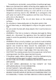
CLEARANCES Installation clearances and protection of combustible surfaces shall comply with the current local regulations e.g. AS/NZS5601.1 (latest edition) - Gas Installations code. Figure 2a A B F C E G 650 mm 450 mm D The thermal protection barrier must be: • removable with the use of a tool for installation and service; • heat-resistant; • made from low thermal conductivity material.
(*) From top of countertop (**) Between the back edge of the cut-out and the back of the countertop. (***) From the side edge of the cut-out to any vertical combustible surface. If this distance is less than 200 mm, the surface shall be protected (in accordance with AS/NZS5601.1) to a height of not less than 150 mm above the hob for the full dimension (width or depth) of the cooking surface area.
FASTENING THE COOKTOP Figure 3a Each cooktop is provided with an installation kit including R brackets and screws for fasteningR the cooktop to benches from 30 to 40mm thick. The kit includes four “F” type brackets (for the front of the cooktop), three “R” type brackets (for the rear of the cooktop) and seven self-threading screws “S”. F F ■■ Cut the unit according to the dimensions in fig. 3a. ■■ Stretch gasket “G” over the edge of the hole made, being careful to overlay the junction edges (fig. 3b).
GAS SUPPLY ■■ ■■ For Natural Gas the gas supply must be regulated to obtain a pressure of 1 kPa with the triple-ring (TR) burner operating at the maximum. ■■ For ULPG models connect the gas supply directly to the appliance test point adaptor (supplied with the conversion kit) and ensure that the supply pressure is regulated to 2.75 kPa. ■■ Do NOT force the ”elbow“ rotation prior to loosening nut. ■■ Do NOT over tighten the nut at the ”elbow“. 1.
4. Turn on the appliance gas controls and light each burner. Check for a well defined blue flame without any yellow tipping. If any abnormality is evident then check that the burner flame spreader and burner cap/s are both located properly. 5. Check the minimum burner setting by quickly rotating the gas control knob from the maximum to the minimum position, the flame must not go out. If adjustment is required carry out the “MINIMUM BURNER SETTING ADJUSTMENT” procedure described below. 6.
TABLE FOR THE CHOICE OF THE INJECTORS Natural Gas ULPG 1.0 2.75 Test Point Pressure [kPa] BURNER Auxiliary (AUX) Injector Orifice Dia. [mm] Gas Consumption [MJ/h] Injector Orifice Dia. [mm] Gas Consumption [MJ/h] 0.92 4.20 0.56 4.20 Semi-rapid (SR) 1.17 6.60 0.70 6.20 Rapid (R) 1.54 11.75 0.98 12.20 Triple-ring (TR) 1.68 13.70 1.04 14.10 (Note: Gas type sticker and data plate are attached to the underside of the base of the appliance.
and replace with test point adaptor (see figs. 4a, 4b). ■■ Auxiliary, semi-rapid and rapid burner If the cooktop is suitable for use with Universal LPG and must be converted for use with Natural gas, before connecting to the gas main remove the appliance test point adaptor and replace with gas regulator (see figs. 4a, 4b). J NOTE: Gas regulator and test point adaptor are supplied with the appliance (packed with conversion kit).
MINIMUM BURNER SETTING ADJUSTMENT Check whether the flame spreads to all burner ports when the burner is lit with the gas tap set to the minimum position. If some ports do not light, increase the minimum gas rate setting. Check whether the burner remains lit even when the gas tap is turned quickly from the maximum to the minimum position. If the burner does not remain lit, increase the minimum gas rate setting. The procedure for adjusting the minimum gas rate setting is described below.
USE and CARE CAUTION: ■■ This appliance must be used only for the task it has explicitly been designed for, that is for domestic cooking of foodstuffs. Any other form of usage is to be considered as inappropriate and therefore dangerous. Do not use this appliance as a space heater. ■■ Do NOT place combustible materials or products on this appliance at any time. Do NOT use or store flammable materials near this appliance. ■■ Do NOT spray aerosols in the vicinity of this appliance while it is in use.
DESCRIPTION OF TOUCH-CONTROLS 1. 2. 3. 4. 5. 6. 7. 8. 9. 10. Child lock safety button (buttons lock) Timer display decrease button Timer display increase button Cooking end programmer/cooking timer setting button Front left cooking zone button Rear left cooking zone button Central cooking zone button Rear right cooking zone button Front right cooking zone button Timer display (h.mm - hour.minutes) NOTE: Each press of a touch-control button is confirmed by an audible beep.
USING GAS BURNERS ■■ Check that the electricity is switched on to allow spark ignition. ■■ Make sure that all controls are turned to “ ■■ The gas flow to the burner is controlled by a tap incorporating a safety cut-off valve. ■■ You control the flow by turning the knob indicator to line up with the following symbols: ” (burner off).
LIGHTING THE BURNERS To ignite the burner, the instructions are to be followed: 1. 2. 3. following Press in the corresponding knob and turn counter-clockwise (fig. 10) to the ” full flame position marked by the “ symbol (fig. 9); press and hold the knob to light the burner (the green indicator light on the knob will blink to show that burner ignition is in progress). In the case of a mains failure light the burner with a match or lighted taper.
IMPORTANT NOTE: The following functions are only enabled when the hob is supplied by the electrical mains. If electrical power is not present these functions are not available. OPERATION TIME LIMIT OF THE COOKING ZONES If no operations are carried out, all cooking zones are switched off automatically after a maximum operating time of 6 hours. After a burner has been extinguished, to restore normal operation return the knob to the “ ” position (off).
PROGRAM FOR AUTOMATIC SWITCHING OFF OF A COOKING ZONE This function makes it possible to program a cooking time from 1 minute to 3 hours 59 minutes, in order to switch off one or more cooking zones automatically. With the burner lit: ■■ Select the cooking zone by pressing the related button (button 5, 6, 7, 8 or 9 in fig. 8); the associated indicator light will start blinking. ■■ Press timer button The timer display will show “0.06 ” ” if you press the button or “0.
COOKING TIMER SET-UP The cooking timer emits an audible notification signal after a maximum cooking time of 9 hours 59 minutes. To activate this function: ■■ Press the button (the timer shows “0.00 ” in blinking mode and also the related indicator light blinks). ■■ Press the or button within approximately 10 seconds to set the required cooking time. The timer display will show “0.06 ” if you press button or “0.04 ” if you press (each subsequent press increases or decreases the time by 1 minute).
COOKING HINTS FOR GAS HOBS ■■ The burner must be chosen according to the diameter of the pans and energy required. ■■ The largest can be used for boiling, to seal meat or foods that are cooked quickly, and the smallest for stews and sauces. ■■ Always ensure that you use the correct size of saucepan. ■■ For fast boiling, make sure the flame just reaches the edge of the pan. Flames going up the side of the pan means wasted heat and the contents of the pan will take longer to boil.
Figure 13 WOK STAND (figs. 14 - 15) This special grille for woks should be placed over the pan-rest for the triple-ring compact, triple ring or Dual burner (depending on models). Warning: ■■ The flat-bottomed pans are to be placed directly onto the pan-support. ■■ To use the WOK, you must place the wok stand in the CORRECT position as shown. IMPORTANT: The special grille for wok pans MUST BE PLACED ONLY over the pan-rest for the triple-ring compact, triple ring or Dual burner (depending on models).
Do not place anything, e.g. flame tamer, asbestos mat, between pan and pan support as serious damage to the appliance may result. Do not remove the pan support and enclose the burner with a wok stand as this will concentrate and deflect heat onto the hotplate. Do not use large pots or heavy weights which can bend the pan support or deflect flame onto the hotplate. Locate pan centrally over the burner so that it is stable and does not overhang the appliance.
CLEANING and MAINTENANCE GENERAL ADVICE ■■ Before you begin cleaning, you must ensure that the appliance is switched off and disconnected from the electrical power supply. ■■ Important: The use of suitable protective clothing/gloves is recommended when handling or cleaning of this appliance. ■■ Under no circumstances should any external covers be removed for servicing or maintenance except by suitable qualified personnel.
ENAMELLED PARTS ■■ All the enamelled parts must be cleaned with a sponge and soapy water only or other non-abrasive products. ■■ Dry preferably with a soft cloth. ■■ If acid substances such as lemon juice, tomato conserve, vinegar etc. are left on the enamel for a long time they will etch it, making it opaque. GAS TAPS ■■ In the event of operating faults in the gas taps, call the Service Department. IMPORTANT WARNING NEVER unscrew the burner plate fixing screws (fig. 17).
BURNERS ■■ ■■ ■■ ■■ ■■ ■■ These parts can be removed and cleaned with appropriate products. After cleaning, the burners and their flame spreaders must be well dried and correctly replaced. Check that the electrode/s “S” (figs. 18, 20) next to each burner is/are always clean to ensure trouble-free sparking. Check that the probe/s “T” (figs. 18, 20) next to each burner is/are always clean to ensure correct operation of the safety valves. Both the probe and ignition plug must be very carefully cleaned.
C F T S Figure 18 Figure 19 F1 S T Figure 20 A B Figure 21 Figure 22 29
PAN SUPPORTS ■■ ■■ ■■ ■■ These parts can be removed and cleaned with appropriate products. After cleaning, they must be well dried and correctly replaced (fig. 23). It is very important to check that the pan supports have been correctly positioned. Failure to do so can cause serious problems. The pan supports shall be level and must not rotate.
SERVICE AND MAINTENANCE If the ignition spark fails to ignite or does not light the gas, check the following items before calling our Customer Service Centre to obtain the nearest Authorised Delonghi Service Agent: ■■ Burner is reassembled and located correctly. ■■ Spark electrode and white ceramic are clean and dry. ■■ 230 or 240 VAC power supply is connected. Contact the local gas utility or our Customer Service Centre to obtain the nearest Authorized Delonghi Service Agent.
D escri ptions and illust r at i ons i n t hi s bookl et ar e g i v e n a s s i mp l y i n d i c a t i v e . T h e manufa ctur er r es er ves t he r i ght , consi der i n g t h e c h a ra c t e ri s t i c s o f t h e models described here, at any time and without notice, to make eventual necessary mo d i fi ca tions for the i r const r uct i on or f or com m e rc i a l n e e d s . w w w.d e lo n g h i.c o m.a u w w w.d e lo n g h i.c o .n z Cod.