
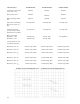
Specifications


16
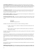
is called flyback current. Figure 2 shows the nature of the motor current which is composed of
both battery current and the inductive flyback current. It should be noted that the average motor
current measured will be greater than the average battery current. The SCR control, in effect, con-
verts battery current at battery volts into a higher motor current and a lower motor volts.
The time for the next ON and OFF cycle to start is determined by the time that the control
card takes to oscillate. This frequency of oscillation is controlled by the potentiometer in the accel-
erator and automatic circuitry in the card. Slow speed is obtained by having maximum ohms in the
potentiometer. As the resistance in the potentiometer decreases, the speed of the motor increases.
The SCR circuit is capable of delivering approximately 95% speed. For full speed operation, the lA
contactor is closed to apply full battery voltage across the motor.
CONTROL FEATURES
OSCILLATOR - the oscillator section of the card has two adjustable features and one fixed feature.
With the accelerator potentiometer at maximum ohms, the creep speed can be adjusted by the
handset unit. Top speed is fixed by card and is
obtained with the accelerator potentiometer at
minimum ohms. The % ON time has a range of
approximately 5 to 95 percent. The center
operating condition of the oscillator is at 50
percent ON time with a nominal l.8 milliseconds
ON time and l.8 millisecond OFF time. This
corresponds to a maximum operating frequency
of about 300 hertz. At creep the ON time will
decrease to approximately 0.8 milliseconds while
OFF time will become in the order of 20 milli-
seconds. At full SCR operation, this condition
will be reversed (short OFF time, long ON time).
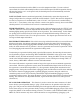
This variation of ON and OFF time of the
oscillator produces the optimum frequencies
through the SCR range. The frequency curve of
the oscillator is shown in Figure 3.
The rate at which the oscillator may increase its percent ON time is limited by Controlled
Acceleration. The minimum time required to go from creep speed to 80-85% on time point may be
varied by the C/A trimpot on the card, adjustable from approximately 0.1 seconds to 22.0 seconds.
CURRENT LIMIT - This circuit monitors motor current by utilizing a sensor in series with the
armature. The information detected across the sensor is fed back to the card so current may be
limited to a pre-set value. If heavy load currents are detected, this circuit overrides the oscillator and
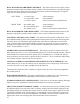
limits the average current to a value set by function 4 of the handset. The C/L setting is based on the
maximum thermal rating of lREC and the peak voltage on the capacitor. Because of the flyback
current through 3REC, the motor current usually runs 2 to 3 times battery current. See current limit
curves for available current and adjustment range.
Figure 3