DFS 901SS Professional cooker GB Users Operating Instructions Before operating this cooker, please read these instructions carefully
Dear Customer Thank you for choosing one of our appliances which has been carefully designed and built by our specialist staff and thoroughly tested to satisfy your cooking requirement. We suggest that you read this Instruction Booklet so that you will understand fully how to operate the appliances. Please keep the booklet handy. You may wish to refer to it at a later date.
Contents Model DFS 901SS Page Number Introduction . . . . . . . . . . . . . . . . . . . . . . . . . . . . . . . . . . . . . . . . . . . . . . . . . . . . . 4 Features and technical data . . . . . . . . . . . . . . . . . . . . . . . . . . . . . . . . . . . . . . . . . 5 Control panel . . . . . . . . . . . . . . . . . . . . . . . . . . . . . . . . . . . . . . . . . . . . . . . . . . . . 6 Electronic clock/alarm . . . . . . . . . . . . . . . . . . . . . . . . . . . . . . . . . . . . . . . . . . . . .
Introduction Congratulations on your purchase of this Delonghi gas cooker which has been carefully designed and produced to give you many years of satisfactory use. Before using this appliance it is essential that the following instructions are carefully read and fully understood. We would emphasise that the installation section must be fully complied with for your safety to ensure that you obtain the maximum benefits from your appliance. Assembling the backguard 1.
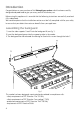
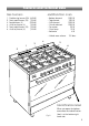
Features and technical data Gas burners 1. 2. 3. 4. 5. 6. Multifunction oven Double-ring burner (PB) Semi-rapid burner (SR) Rapid burner (R) Auxiliary burner (A) Semi-rapid burner (SR) Auxiliary burner (A) 3,45 kW 1,90 kW 2,95 kW 1,00 kW 1,90 kW 1,00 kW – Bottom element – Top element – Grill element – Circular element – Fan motor – Oven lamp – Rotisserie 2050 W 1250 W 2200 W 2500 W 25 W 15 W 4W – Usable oven volume 100 dm3 4 5 3 6 1 2 Identification label Fig.
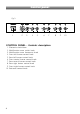
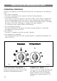
Control panel Fig. 3 A U T O 1 2 3 4 5 6 7 CONTROL PANEL - Controls description 1. 2. 3. 4. 5. 6. 7. 8. 9. 10.
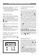
How to use the electronic clock The electronic programmer is a device with the following functions: – 24 hours clock with illuminated display – Timing of oven cooking with automatic switch-off (max. 99 minutes). Electronic clock Upon immediate connection of the oven or after a mains failure, three zeros will flash on the programmer panel. To set the clock it is necessary to push the button and then, within 7 seconds, the or button until you have set the correct time.
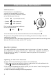
How to use the hob burners Hob burners Each hob burner is controlled by a separate gas tap operated by a control knob (fig. 5) which has 3 positions marked on the control panel, these are: – Symbol ● : tap closed (burner off) – Symbol : High (maximum) – Symbol : Low (minimum) Push in and turn the knob anti-clockwise to the selected position. Low High Fig. 5 To turn the burner off, fully rotate the knob clockwise to the off position: ●.
Choice of burner The burner must be choosen according to the diameter of the pans and energy required. Burners Pan diameter Auxiliary Semi-rapid Rapid Double-ring 16 cm 16 ÷ 22 cm 20 ÷ 24 cm up to 30 cm Fig. 6 Saucepans with handles which are excessively heavy, in relationship to the weight of the pan, are safer as they are less likely to tip. Pans which are positioned centrally on burners are more stable than those which are offset.
How to use the Multifunction oven OPERATING PRINCIPLES Heating and cooking in the MULTI-FUNCTION oven are obtained in the following ways: a. by normal convection The heat is produced by the upper and lower heating elements. b. by forced convection A fan sucks in the air contained in the oven muffle, which sends it through the circular heating element and then sends it back through the muffle.
OVEN LIGHT By setting the knob to this position, only the oven light comes on (15 W). It remains on in all the cooking modes. TRADITIONAL CONVECTION COOKING The upper and lower heating elements come on. The heat is dispersed by natural convection and the temperature must be set to between 50° and 225°C via the thermostat knob. The oven must be preheated before cooking. Recommended for: Food that requires the same degree of cooking both inside and out, for example roasts, spare pork ribs, meringues etc.
HOT AIR COOKING The circular element and fan come on. The heat is dispersed by forced convection and the temperature can be regulated to between 50° and 225°C via the thermostat knob. The oven does not require preheating. Recommended for: Food which has to be well-cooked outside and soft or rosy inside, for example lasagne, lamb, roast beef, whole fish etc. VENTILATED GRILL COOKING The infrared grill element and the fan come on.
COOKING ADVICE STERILIZATION Sterilization of foods to be conserved, in full and hermetically sealed jars, is done in the following way: a. Set the switch to position . b. Set the thermostat knob to position 185 °C and preheat the oven. c. Fill the dripping pan with hot water. d. Set the jars onto the dripping pan making sure they do not touch each other and the door and set the thermostat knob to position 135 °C.
GRILLING AND “AU GRATIN” Grilling may be done without the roasting jack on position of the switch, because the hot air completely envelops the food that is to be cooked. Set the thermostat to position 175 °C and after having preheated the oven, simply place the food on the rack. Close the door and let the oven operate with the thermostat on position 175 °C, until grilling is done. Adding a few dabs of butter before the end of the cooking time gives the golden “au gratin” effect.
Rotisserie (Fig. 10) This is used for spit roasting under the grill and comprises: – an electric motor fitted to the rear of the oven – a stainless steel skewer provided with slide-out heatless handgrip and two sets of adjustable forks – a skewer support to be fitted in the middle runner. The rotisserie motor is operated by the oven switch (Fig. 9). Fig. 9 Use of the rotisserie – Insert the tray into the lowest rack holders of the oven and insert the rod support into the intermediate rack holders.
Important notes Installation, and any demonstration, information or adjustments are not included in the warranty. The cooker must be installed by a qualified person in accordance with the Gas Safety (Installation and Use) (Amendment) Regulations 1990 and the relevant building/l.E.E Regulations. Failure to install the appliance correctly could invalidate any manufacturers warranty and lead to prosecution under the above quoted regulation. In the UK C.O.R.G.
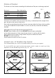
Do’s and do not’s Do’s and do not’s • Do always grill with the oven door closed. • Do read the user instructions carefully before using the cooker for first time. • Do allow the oven to heat for one and a half hours, before using for the first time, in order to expel any smell from the new oven insulation, without the introduction of food. • Do clean your oven regularly. • Do remove spills as soon as they occur. • Do always use oven gloves when removing food shelves and trays from the oven.
Care and maintenance Important: As a safety measure, before you start cleaning the cooker be sure to disconnect it from the mains supply. Do not use a steam cleaner because the moisture can get into the appliance thus make it unsafe. Cleaning the hob Spillage on the hob can usually be removed by a damp soapy cloth. More obstinate stains can be removed by rubbing gently with a soapy scouring pad or mild household cleaner. Burners They can be removed and washed only with soapy water.
Gas taps If a tap becomes stiff, do not force; contact your local COMET Service Centre. Flexible tube From time to time, check the flexible tube connecting the gas supply to the cooker. It must be always in perfect condition; in case of damage arrange for it to be replaced by a C.O.R.G.I. registered installer. Cleaning oven parts after use The oven interior and the chromium plated shelves can be cleaned by damp soapy cloth.
Removal of the inner glass door panel – The inner glass door panel can easily be removed for cleaning by unscrewing the four screws (fig. 11). – When re-assembly ensure that the inner glass is correctly positioned and do not over tighten the screws. Fig. 11 Dishwarmer compartment – The dishwarmer compartment is accessible through the pivoting panel. Fig. 12 Assembling and removing the side racks Hang up the wires racks on the oven walls (fig. 13) Slide the required grid or tray into the guides Fig.
Oven tray The oven tray must be correctly placing on its wire shelf support (fig. 14) then insert into the side runners (fig. 15) Fig. 14 Fig. 15 Changing the oven light 1. Disconnect the electrical power supply (for example, by switching off the main power switch). 2. Unscrew the light cover 3. Fit a new bulb. 4. Refit the cover. Note: Use only bulbs designed to resist up to 300°C with the following characteristics: 15 W, 230 V, type E-14.
Removing the oven door Fig. 16a Please operate as follows: ● ● ● ● Open the door completely. The swivel retainers of the rh and lh hinges (fig. 16a) are hooked onto the metal bar above them (fig. 16b). Lift the oven door slightly. The noch on the bottom of the hinge will disengage (fig. 16c). Now pull the oven door forwards off the appliance. Release both hinge sections from the slots (fig. 16d). Fig.
FOR THE INSTALLER Location This cookers has type “2/1” overheating protection so that it can be installed next to a cabinet. The furniture walls adjacent to the cooker must be made of material resistant to heat. The veneered syntetical material and the glue used must be resistant to a temperature of 120°C in order to avoid ungluing or deformations. The cooker may be located in a kitchen, a kitchen/diner or bed-sitting room but not in a room containing a bath or shower.
Fitting the adjustable feet The adjustable feet must be fitted to the base of the cooker before use. Rest the rear of the cooker an a piece of the polystyrene packaging exposing the base for the fitting of the feet. Fig.
WARNING When raising cooker to upright position always ensure two people carry out this manoeuvre to prevent damage to the adjustable feet (fig. 19). WARNING Be carefull: do not lift the cooker by the door handle when raising to the upright position (fig. 20). Fig. 19 WARNING When moving cooker to its final position DO NOT DRAG (fig. 21). Lift feet clear of floor (fig. 19). Levelling the cooker The cooker may be levelled by screwing the lower ends of the feet IN or OUT (fig. 22). Fig. 20 Fig. 21 Fig.
Stability bracket We recommend a stability bracket is fitted to the cooker. The type shown in fig. 23 can be purchased from most plumbers merchants and do it yourself (D.I.Y.) shops. Existing slot in rear of cooker Brackets Fig.
Provison for ventilation The room containing the cooker should have an air supply in accordance with BS.5540: Part 2: 1989. All rooms require an openable window or equivalent while some rooms require a permanent vent in addition to the openable window. The cooker should not be installed in a bed-sitting room, of volume less than 21 m3.
Gas installation IMPORTANT NOTE This appliance is supplied for use on NATURAL GAS only and cannot be used on any other gas without modification. This appliance is manufactured for conversion to LPG and is supplied with a conversion kit. The cooker must be installed by a qualified person in accordance with the Gas Safety (Installation and Use) (Amendment) Regulation 1990 and the relevant building/l.E.E. Regulations. The following British Standards should be used as reference when installing this appliance.
Gas connection The installation of the cooker to Natural Gas or LP Gas must be carried out by a qualified gas engineer. Installer shall take due account of the provisions of the relevant British Standards Code of Practice, the Gas Safety Regulations and the Building Standards (Scotland) (Consolidation) Regulations issued by the Scottish Development Department. Installation to Natural Gas Installation to Natural Gas must conform to the Code of Practice, etc. The supply pressure for Natural Gas is 20 mbar.
Conversion to LPG 1 - Injectors replacement of top burners To replace the injectors it is necessary to lift the hobtop and proceed as follows: – Remove pan-supports and burners from the hobtop. – Remove the backguard “E”. – Unscrew the two screws “B” and remove the sockets (Fig. 26). – Unscrew the two screws “C” and remove the two side trims and joints pulling upwards. – Pull forwards the hobtop to release it, then lift following arrow “D” (Fig. 26) – Hold the hobtop open by a support.
Flame faulty in primary air Flame correct Flame with excess primary air long, yellow and trembling clear interior blue cone short and sharp too blue interior cone tending to detach CAUSE air regulating tube, too closed correct distance of the tube air regulating tube, too open 3 - Adjusting of the minimum of the top burners Considering that in the minimum position the flame must have a length of about 4 mm and must remain lit even with a quick turn from the maximum position to that of minimum.
Table for the choice of the injectors GB Nominal Reduced Power Power [kW] [kW] By-pass [1/100 mm] Ø injector Auxiliary (A) 1,00 0,30 27 50 3* Semi-rapid (SR) 1,90 0,38 29 67 5,7 * Rapid (R) 2,95 0,60 39 83 fully open * Double-ring 3,45 0,85 47 92 fully open * [1/100 mm] Ring opening [mm] G 20 20 mbar By-pass [1/100 mm] adjustable BURNERS Cat: II 2H3+ G 30 - 28-30 mbar G 31 - 37 mbar Ø injector [1/100 mm] Ring opening [mm] 72 1* 100 2* 125 3* 135 5* * = Reference va
Lubrication of the gas taps Should it be found that the gas taps are difficult to turn, most probably they require lubrication. This should be done immediately this problem has been noticed as follows. – Turn off the gas supply to cooker. – Remove all control knobs. – Remove control panel. – Unscrew the two screws which mounts the gas tap to the gas rail. – Remove the circlip and ignition switch from the front of the gas tap. – Disassemble the body of the tap.
Electrical installation For your safety please read the following information: This appliance must be installed by a qualified technician according with the current local regulations and in compliance with the manufacturer instructions. All electrical wiring must be in compliance with the appropriate IEE regulations and carried out by a qualified electrician . Before installing the cooker the electricity must be turned off.
ß10 DFS 901SS cooker Ed. 6 - Cod.