GSS601 gas cooker GB Users Operating Instructions Before operating this cooker, please read these instructions carefully
Dear Customer Thank you for choosing one of our appliances which has been carefully designed and built by our specialist staff and thoroughly tested to satisfy your cooking requirement. We suggest that you read this Instruction Booklet so that you will understand fully how to operate the appliances. Please keep the booklet handy. You may wish to refer to it at a later date.
Contents Model GSS601 Page Number Introduction . . . . . . . . . . . . . . . . . . . . . . . . . . . . . . . . . . . . . . . . . . . . . . . . . . . . . 4 Features and technical data . . . . . . . . . . . . . . . . . . . . . . . . . . . . . . . . . . . . . . . . . 5 Electronic clock/Alarm . . . . . . . . . . . . . . . . . . . . . . . . . . . . . . . . . . . . . . . . . . . . . 6 How to use the hob burners . . . . . . . . . . . . . . . . . . . . . . . . . . . . . . . . . . . . . . . . 7 Hob burners . . . . .
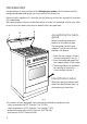
Introduction Congratulations on your purchase of this Delonghi gas cooker which has been carefully designed and produced to give you many years of satisfactory use. Before using this appliance it is essential that the following instructions are carefully read and fully understood. We would emphasise that the installation section must be fully complied with for your safety to ensure that you obtain the maximum benefits from your appliance.
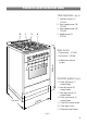
Features and technical data Gas burners 1. 2. 3. 2 1 3 4 4. (Fig. 2) Auxiliary burner (A) 1.00 kW Semi-rapid burner (SR) 1.90 kW Semi-rapid burner (SR) 1.90 kW Rapid burner (R) 3.15 kW Gas oven – Oven burner - 3.70 kW – Grill burner - 2.55 kW 11 10 5 8 6 7 9 900 mm – Usable oven volume 61 dm3 Control panel (Fig. 2) 600 mm 600 5. Front left burner (1) control knob 6. Rear left burner (2) control knob 7. Rear right burner (3) control knob 8. Front right burner (4) control knob 9.
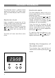
Electronic Clock/Alarm The electronic alarm is a device which groups the functions of 24 hours clock with illuminated display and 99 minutes alarm. Electronic clock Upon immediate connection of the cooker or after a mains failure, three zeros will flash on the programmer panel. To set the clock it is necessary to push the button and then, within 7 seconds, the or button until you have set the correct time. The clock will show zero after a mains failure.
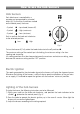
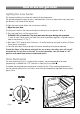
How to use the hob burners Hob burners Each hob burner is controlled by a separate gas tap operated by a control knob (fig. 4) which has 3 positions marked on the control panel, these are: – Symbol ● : tap closed (burner off) – Symbol : High (maximum) – Symbol : Low (minimum) Push in and turn the knob anti-clockwise to the selected position. Low High Fig. 4 To turn the burner off, fully rotate the knob clockwise to the off position: ●.
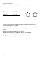
Choice of burner The burner must be choosen according to the diameter of the pans and energy required. Burners Pan diameter Auxiliary Semi-rapid Rapid 16 cm 16 ÷ 22 cm up to 30 cm Fig. 5 Saucepans with handles which are excessively heavy, in relationship to the weight of the pan, are safer as they are less likely to tip. Pans which are positioned centrally on burners are more stable than those which are offset.
How to use the gas oven Lighting the oven burner The thermostat allows the automatic control of the temperature. The gas delivered to the oven burner is controlled by a two way thermostatic tap (oven and grill burners) with flame-failure device. To light the oven burner follow the instructions carefully: 1) Open the oven door 2) Lightly press and turn the thermostat knob anti-clockwise to max position (★ fig. 6). 3) Press the knob firmly until the burner lights.
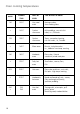
Oven cooking temperatures 10 MARK APPROX. TEMP. HEAT OF OVEN TYPE OF DISH TO COOK 130 130°C Very cool oven Meringue cakes, slow cooking items • 140°C Cool or slow oven Milk puddings, very rich fruit cakes, i.e., Christmas 155 155°C Cool or slow oven Stews, casseroles, braising, rich fruit cakes, i.e., Dundee • 165°C Warm oven Biscuits, rich plain cakes i.e., Madeira. Low temp.
How to use the grill Lighting the grill burner Do not grill with oven door closed. Always fit the heat shield supplied with the cooker under the front panel before commencing operations (Fig. 10). WARNING. The heat shield and the oven door reaches a very high temperature whilst in use. Keep children away and allow to cool before removing. The grill burner generates infra-red rays for grilling. To light the grill burner follow the instructions carefully: 1) Open the oven door.
Notes: – The grill burner has only one setting, that is full-on – It is important that the heat shield is fitted the correct way up, as shown in the figure 10. Fig. 10 Oven light The oven is equipped with a oven light which is operated by the light control knob (fig. 11) Replacement of the light bulb if the light bulb needs replacement disconnect the cooker from the electrical supply. Unscrew the bulb glass cover and replace the bulb with a type SES 15 Watt 300°C.
Important notes Installation, and any demonstration, information or adjustments are not included in the warranty. The cooker must be installed by a qualified person in accordance with the Gas Safety (Installation and Use) (Amendment) Regulations 1990 and the relevant building/l.E.E Regulations. Failure to install the appliance correctly could invalidate any manufacturers warranty and lead to prosecution under the above quoted regulation. In the UK C.O.R.G.
Do’s and do not’s Do’s and do not’s • Do always grill with the oven door half-close (see figure 10). • Do always remove the detachable handle when using the grill pan. • Do read the user instructions carefully before using the cooker for first time. • Do allow the oven to heat for one and a half hours, before using for the first time, in order to expel any smell from the new oven insulation, without the introduction of food. • Do clean your oven regularly. • Do remove spills as soon as they occur.
Care and maintenance Important: As a safety measure, before you start cleaning the cooker be sure to disconnect it from the mains supply. Cleaning the hob Spillage on the hob can usually be removed by a damp soapy cloth. More obstinate stains can be removed by rubbing gently with a soapy scouring pad or mild household cleaner. Black burners (“oxi-black” coating) They can be removed and washed only with soapy water. Detergents can be used but must not be abrasive or corrosive.
Assembling and removing the side racks Hang up the wires racks on the oven walls (fig. 12) Slide the required grid or tray into the guides Removal of the inner glass door panel The inner glass door panel can easily be removed for cleaning by unscrewing the two screws. Figure 13. During re-assembly, ensure that the inner glass is correctly aligned and do not over tighten the screws.
Removing the oven door To facilitate oven cleaning, it is possible to remove the door. Please follow the instructions carefully: ● Open the door completely. ● Push down the lever “L” and, keeping it in this position, slowly close the door in order to block the hinge (fig. 15). ● Grip the door (as indicated in fig. 16) and, while closing it, release the two hinges as shown in fig. 17.
FOR THE INSTALLER Location 450 mm 650 mm This cookers has class 2/1 overheating protection so that it can be installed next to the cabinet where the height is greater than the cooker (minimum distance 50 mm - fig. 18). The furniture walls adjacent to the cooker must be made of material resistant to heat. The veneered syntetical material and the glue used must be resistant to a temperature of 120°C in order to avoid ungluing or deformations.
Stability bracket We recommend a stability bracket is fitted to the cooker. The type shown in fig. 19 can be purchased from most plumbers merchants and do it yourself (D.I.Y.) shops. Wall fixing Floor fixing Existing slot in rear of cooker Brackets Dotted line showing the position of cooker when fixed 3 Outline of cooker backplate at the engagement slot Fig.
Provison for ventilation The room containing the cooker should have an air supply in accordance with BS.5540: Part 2: 1989. All rooms require an openable window or equivalent while some rooms require a permanent vent in addition to the openable window. The cooker should not be installed in a bed-sitting room, of volume less than 21 m3.
Gas installation IMPORTANT NOTE This appliance is supplied for use on NATURAL GAS only and cannot be used on any other gas without modification. This appliance is manufactured for conversion to LPG and is supplied with a conversion kit. The cooker must be installed by a qualified person in accordance with the Gas Safety (Installation and Use) (Amendment) Regulation 1990 and the relevant building/l.E.E. Regulations. The following British Standards should be used as reference when installing this appliance.
Gas connection The installation of the cooker to Natural Gas or LP Gas must be carried out by a qualified gas engineer. Installer shall take due account of the provisions of the relevant British Standards Code of Practice, the Gas Safety Regulations and the Building Standards (Scotland) (Consolidation) Regulations issued by the Scottish Development Department. Installation to Natural Gas Installation to Natural Gas must conform to the Code of Practice, etc. The supply pressure for Natural Gas is 20 mbar.
Conversion to LPG 1 - Injectors replacement of top burners To replace the injectors it is necessary to lift the hobtop and proceed as follows: – Remove pan-supports and burners from the hobtop. – Remove the backguard “E”. – Unscrew the two screws “B” and remove the sockets (Fig. 23). – Unscrew the two screws “C” and remove the two side trims and joints pulling upwards. – Pull forwards the hobtop to release it, then lift following arrow “D” (Fig. 23) – Hold the hobtop open by a support (Fig. 24).
Flame faulty in primary air Flame correct Flame with excess primary air long, yellow and trembling clear interior blue cone short and sharp too blue interior cone tending to detach CAUSE air regulating tube, too closed correct distance of the tube air regulating tube, too open 3 - Adjusting of the minimum of the top burners Considering that in the minimum position the flame must have a length of about 4 mm and must remain lit even with a quick turn from the maximum position to that of minimum.
Table for the choice of the injectors GB Nominal Reduced Power Power [kW] [kW] By-pass [1/100 mm] Ø injector Auxiliary (A) 1,00 0,30 27 50 3* Semi-rapid (SR) 1,90 0,38 29 67 5,7 * Rapid (R) 3,15 0,60 39 86 fully open * Oven 3,70 0,70 42 92 fully open * Grill 2,55 – – 80 fully open * [1/100 mm] Ring opening [mm] G 20 20 mbar By-pass [1/100 mm] adjustable BURNERS Cat: II 2H3+ G 30 - 28-30 mbar G 31 - 37 mbar – Ø injector [1/100 mm] Ring opening [mm] 72 1* 100 2*
4 - Replacement of the oven burner injector According to the type of gas, the oven injector must be similarly replaced, as stated on the “Injector table”, operating as follows: – remove the oven bottom – unscrew the burner fixing screw (Fig. 27) – slip the burner itself from the oven (Fig. 28). Take care not to damage the wire to the ignition electrode and the safety valve probe. – remove the injector from the connection and replace it with the correct one (fig. 28). Fig. 27 Fig.
6 - Primary air of the oven burner With a screwdriver untighten the screw (fig. 31) and move the air ring forward or backward to close or open the air flow, according to the “Injector table”. Light the burner and check the flames. 7 - Primary air of the grill burner With a screwdriver untighten the screw (fig. 32) and turn the air ring to close or open the air flow, according to the “Injector table”. Light the burner and check the flames. Fig. 31 Ring opening (see “Injector Table” on page 25) Fig.
8 - Regulating of the oven minimum This adjustment is for the oven burner only (as the grill burner is fixed input) operating on the thermostat as follows: – Light the oven taking the knob to Max. position. – remove the knob and by a thin screwdriver (3 mm section - 100 mm long) unscrew about a half turn the screw by-pass “G’, passing through the front panel hole (fig. 33) – fit the knob and let the oven heat for 10 minutes, then take the knob to position 130 allowing the thermostat to work under by-pass.
Lubrication of the gas taps Should it be found that the gas taps are difficult to turn, most probably they require lubrication. This should be done immediately this problem has been noticed as follows. – Turn off the gas supply to cooker. – Remove all control knobs. – Remove control panel. – Unscrew the two screws which mounts the gas tap to the gas rail. – Remove the circlip and ignition switch from the front of the gas tap. – Disassemble the body of the tap.
Electrical installation For your safety please read the following information: This appliance must be installed by a qualified technician according with the current local regulations and in compliance with the manufacturer instructions. This appliance is supplied with a 13 amp three pin mains plug with a 3 amp fuse fitted. Should the fuse require replacement, it must be replaced with a fuse rated at 3 amp and approved by ASTA or BSI to BS 1362.
A properly earthed three pin plug (fused at 3 amps, to BS 1362 ASTA approved) must be used. As the colours of the wires in the mains lead of this appliance may not correspond with the coloured markings identifying the terminals in your plug, proceed as follows. The wire which is coloured GREEN & YELLOW must be connected to the terminal in the plug which is marked with letter "E" or by the Earth symbol or coloured GREEN & YELLOW.
rif. 1458.ß11 GSS601 gas cooker Ed. 4 - Cod.