® Topo USA 4.
Table of Contents Table Of Contents TABLE OF CONTENTS ............................................................................................................................................................ 1 WELCOME .................................................................................................................................................................................... 8 W ELCOME TO TOPO USA 4.0 ..................................................................................
Table of Contents U SING THE SECONDARY M AP...................................................................................................................................................22 Accessing Data Collections................................................................................................................................................22 Additional Facts About Split-Screen Functionality................................................................................................
Table of Contents PRINTING TIPS............................................................................................................................................................................50 For Laser Printers ...............................................................................................................................................................50 For Black-and-White Printers................................................................................................
Table of Contents Points in Rectangles, Circles, and Arcs...........................................................................................................................64 Points in Point Draw Objects ............................................................................................................................................65 Points in MapNotes..........................................................................................................................................
Table of Contents To Place a Circle at a Specific Location.........................................................................................................................89 RECTANGLES: DRAWING, EDITING, AND PLACING...............................................................................................................89 To Draw a Rectangle...........................................................................................................................................................
Table of Contents A UTOMATIC PAN..................................................................................................................................................................... 113 To Pan the Map Automatically........................................................................................................................................113 LOGGING......................................................................................................................................
Table of Contents SETTING M AP FEATURE PREFERENCES................................................................................................................................ 132 To Set Basic Map Feature Preferences..........................................................................................................................132 To Set Custom Features................................................................................................................................................
Welcome Welcome Welcome to Topo USA 4.0 Tip: To view Help, click a book once to read its overview. Double -click a book to read its overview and view all associated topic pages. Click a topic to view its contents. With Topo USA 4.0, you can perform the follow ing functions and more: • Use the QuickSearch Find feature to locate a city or town, a major point of interest, street address, ZIP Code, or coordinate point.
Welcome To Run Topo USA 4.0 Use the following steps to access Topo USA 4.0. 1. Insert a Sat 10, 3-D TopoQuads, or Topo USA 4.0 data disc into your CD/DVD-ROM. 2. If you installed a desktop shortcut, double -click the Topo USA 4.0 icon. OR From the Start menu, point to Programs , point to DeLorme , point to Topo USA 4.0, and then click Topo USA 4.0. Exiting Topo USA 4.0 To exit the program, click the close button in the upper-right corner of the screen.
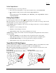
Welcome Region 3 Great Lakes and Plains IA, IL, IN, KS, MI, MN, MO, ND, NE, SD, WI Region 4 Southwest AZ, NM, OK, TX Region 5 Mountain States Region CO, ID, MT, UT, WY Region 6 Pacific West AK, CA, HI, NV, OR, WA Topo USA 4.0 File Directories Topo USA 4.0 allows you to save route files, draw files, print files, and so forth in designated directories. The table below describes the different file types the program supports, which default directory each file type is saved in, and the file extension(s).
Welcome Saving Topo USA Data to Your Hard Disk Drive Your Topo USA data can be saved to your hard disk drive so that it is readily available without inserting it into your CD/DVD-ROM drive when you need it. To Save Topo USA Data Use the following steps to save Topo USA data to your hard disk drive. 1. Insert the Topo USA data disc into your CD/DVD-ROM drive. 2. From the Start menu, click Run. 3.
Welcome How do I transfer waypoints? With Topo USA 4.0 you can upload and download waypoints between your computer and your handheld device, if it has that capability. For more information, see the following topics: • Uploading to a GPS Receiver on page 115 • Downloading from a GPS Receiver on page 115 • GPS Settings for Third-Party Devices on page 116 How do I bring in maps from another DeLorme program? Routes you create using any of the following DeLorme programs can be brought into Topo USA 4.
Welcome What is a project? Topo USA 4.0 lets you save all of the work you have done in the mapping application as a single workspace so you can open it again later. These saved workspaces are called projects. A project consists of the following items: coordinates of the map center, current zoom level, current magnification, map display preferences, any added items: such as draw file(s), route(s), and so forth.
Help Help Help Overview There are several ways to get more information on Topo USA 4.0 features and functionality. On-Screen Help Help is available in the dialog area of Topo USA 4.0 in the form of ToolTips and information boxes. For more information, see On-Screen Help on page 16. Help Menu Click the Help button on the title bar to view the online Help options available with Topo USA 4.0. Then, clic k an item to select it.
Help • If a topic has any secondary index references, a window displays the secondary index options. Click the item of interest to display the topic. • If you don't find what you're looking for in the index, click the Search tab and try a search for your keyword. Search Use the following steps to search for particular words or phrases within topics in the Help system. • While in the Help system, click the Search tab.
Help Tip: Before clicking Print, expand any links in the topic which include information you want to print within your topic. • While in the Help system, the pointer changes to a hand when it passes over text or graphics that you can click for more information. • The Help Topics window is a standard window that can be moved or resized. To exit Help, click the close button in the upper-right corner of the screen.
Help ToolTips When you point to any of the Topo USA 4.0 tools for a few seconds, a short label (ToolTip) displays on your screen describing the tool. ToolTips also display in Topo USA 4.0 windows and dialog boxes when you point to a button, icon, or other feature. Information Boxes Several of the Topo USA 4.0 tabs contain information boxes that often display to the left of the Overview Map (the small map in the lower-right corner of your screen).
Basic Functions Basic Functions Basic Functions Overview Map control in Topo USA 4.0 is accomplished by using standard mouse point-and-click functionality and the Control Panel tools. Right-click options provide flexibility for labeling, routing, getting information, and so forth. For more information, see other Basic Functions topics. If they are not currently displaying, double-click the Basic Functions book. To Control the Map The following list details the basic functions for controlling map movement.
Basic Functions Use the following steps to zoom out. 1. Drag the mouse in an up-left direction on the map. A staircase with a small square displays on the screen. 2. Continue dragging the mouse in an up-left direction. The small square moves up the steps, one step per zoom level. A label displays the zoom level to the bottom-right of the staircase. 3. Once you reach the desired zoom level you want to display, release the mouse button. The map view adjusts to display the appropriate level of detail.
Basic Functions Control Panel The Control Panel, located to the right of the map view, displays information pertinent to the current map view and map cursor position. It also includes zoom and map pan buttons. Zoom Level—The current zoom level of the map view; ranges between 2-0 (maximum zoom-out) and 20-0 (maximum zoom-in). Zoom Tools—Buttons that quickly zoom out three levels, out one level, or in one level. For more information, see Zooming In and Out on page 31.
Basic Functions East, 135 degrees is Southeast, 180 degrees is South, and so forth. For example, when you select 90 degrees from the drop-down list, the map rotates so that 90 degrees (East) is at the top of the screen. To Change the Map Rotation Use one of the following two methods to change the angle of map rotation. • Select an angle from the available drop-down list (in 45 degree increments) OR • Type a specific angle (from 0 to 359 degrees) in the entry field.
Basic Functions Notes: • Measure objects (lines and areas) are saved with the current project. When a new file is created, the measure objects do not display. If you want the same measure objects on your new project, you must recreate them. • When you right-click a measure object, a shortcut menu displays Delete Measurement and Copy to Draw Object options. For more information, see Right-Click Mouse Options on page 24.
Basic Functions Note: The graphic above displays Sat 10 data, available separately from DeLorme. Additional Facts About Split-Screen Functionality The following list details split-window functionality and the interaction between the primary and secondary map windows. • Both windows are centered on the same coordinate position. Panning or rotating the primary map using the tools in the Control Panel causes the same action on both maps.
Basic Functions map at zoom level 8-0 and you click the Zoom Out 1 tool, the secondary map displays at zoom level 5-0 and the primary map at 7-0. • You can use the measure tool in either window and any line or polygon measured in one window also displays in the other window. • The Overview Map is always associated with the primary window and only displays the visible primary map data. • Other tab functionality may be affected by use of the split-screen function.
Basic Functions MapNote Type (Color) Blank MapNote (white) MapNote Label Information A blank label, which you can edit yourself. Note : Once a MapNote is added, its anchor point cannot be moved. However, the text area can be repositioned. For more information, see To Move Right-Click MapNotes on page 29. Convert to Waypoint/Via This option is available when you right-click a waypoint or via on a route. It allows you to switch the selected point from a waypoint to a via, or vice versa.
Basic Functions Info Right-click a point, symbol, feature, or area on the map and then click Info to identify it and view detailed information about it. This information displays in the Overview Map area, to the right of the tabs. Notes: • The type of descriptive information varies, depending on the item you have right-clicked. You can also copy the information and paste it into another program, such as a word processor.
Basic Functions Route: Activate, Hide, Delete, and Profile Route Options • To activate an inactive route, right-click the desired inactive route and then click Activate Route . • To hide a route, right-click the route and then click Hide Route. • To delete a route, right-click the route and then click Delete Route. • To view a cross-sectional, elevation profile of your route, right-click the route and then click Profile Route.
Basic Functions 3. Open or switch to the program where you want to paste the text. 4. Click to select the location where you want to paste the text and then press CTRL+V on your keyboard. OR Right-click the selected location and then click Paste. OR If the program you are pasting information into has a menu bar, under the Edit menu, click Paste . Moving or Deleting MapTags, MapNotes, and Text Labels There are several types of tags, notes, and text labels used in Topo USA 4.0.
Basic Functions Type of item Description edit yourself by using the MapNote/Text Label tool in the Draw Tab. Text labels do not have a background color like other map labeling items. For more information and Placing on page 101. Note: To edit the text, right-click the blank MapNote, click Edit Draw Object, and then edit the text.
Basic Functions To Resize the Map and Tab Area Using the Drag Method The drag method can be used to resize these areas horizontally or vertically. Use the following steps to resize using the drag method. 1. Point to the frame area between the Tab and Overview Map windows. The pointer becomes a . OR Point to the horizontal edge of the Tab or Overview Map window. The pointer becomes a . 2. Drag to resize. 3. To cancel the resize while dragging, press the ESC key on your keyboard.
Basic Functions Zooming In and Out With Topo USA 4.0, you can use the Zoom tools to quickly change the zoom level of the map view. Increasing the zoom level number shows a smaller geographic area at greater detail. Decreasing the zoom level number shows a larger geographic area at lesser detail. To Zoom In/Out Using the Zoom Tools Use the Zoom Tools shown below to zoom quickly. Click the Zoom In 1 tool to increase the detail number to the next full level.
Find Find Find Overview There are two Find options you can use to search for and locate places and other map items in Topo USA 4.0: the QuickSearch and the Advanced functions. • QuickSearch—Search for places, addresses, ZIP Codes, and coordinate positions. If the item you are looking for is not recognized, the Advanced tab displays automatically. • Advanced—Control what you are looking for via the Find field, and where you are looking for it via the Within field while you conduct a more detailed search.
Find Notes: • Use a comma to separate city and state (Atlanta, Georgia), point of interest and state (Space Needle, WA), parts of an address (444 E Pk Drive, Milford, CT or 444 E Pk Dr, 06460), or coordinate points (N 43.8, W 70.2). Tip: Major landmarks or points of interest such as the Space Needle, Yellowstone National Park, Mount Rushmore, and so forth, can be found without using the state as part of the search criteria.
Find To delete MapTags, click the Find tab and then click the Select tool . Note : The Select tool is available on both the QuickSearch and Advanced dialog areas. • To delete one MapTag, click the desired MapTag, and then click the Delete Tag tool OR Right-click the MapTag you want to delete and then click Delete MapTag. • To delete several MapTags, hold down the SHIFT key on your keyboard while clicking the desired MapTags, and then click the Delete Tag tool.
Find closest matching, valid ZIP Code. You can browse through results in either direction to the first (or last) item in the database. • Category—Searches for a category of items within the specified area. For more information on category searches, see Keywords for Category Searches on page 36. Note : In all category searches, the Keywords field is optional. If the Keywords field is left blank, all objects in the selected Within area display in the Results list.
Find 4. Type information in the text fields to the right of the Find and Within fields. The fields available are based on the selected Find and Within fields. Tip: A few fields are optional and you may get better results by leaving them blank. To see if a field is optional, hold your pointer over the text box label or down arrow and read the ToolTip for that field. 5. Click Search or press the ENTER key on your keyboard.
Find Education and Cultural • College • Local Park • Park • School • State Park • University Natural Features • Beach • Canyon • Crater • Desert • Forest • Glacier • Hill • Island • Mountain • River • Stream • Valley • Water Miscellaneous • Cemetery • Hiking • Mine • Note • Park • Object Types • Draw Object • Point • Polygon • Symbol • Tag Roads and Trails 37
Find • Bridge • Exit • Ferry • Foot Trail • Highway • Hiking • Interstate • One Way • Railroad • Road • Street • Trail • Tunnel Travel Amenities • Airport • Exit • Landmark • Rest Area Notes on Category Searches The following list provides notes you may find helpful for performing category searches. • The Keywords field is optional in all Category searches and if left blank, all objects in the Within area display in the Results list. • Keywords are not case-sensitive.
Find • Partial words are recognized when performing a search. For example, when using a keyword such as ATM, search results might include items under categories such as ATM Machine, Weather Atmospheric Conditions, and Window Treatments or Upholstery. Note : This search may not be valid for this product, but serves as an example. • Keywords can be used in any order. You get the same results using Local Road as for Road Local.
Find • There are two types of results lists: Most searches provide a fixed number of results. If all the results do not fit in the screen area, a scroll bar automatically displays. Scroll Bar Browse Buttons Name and ZIP Code searches within the United States, and Area Code/Exchange searches provide results you can browse. This means the entire (appropriate) database displays with the best match highlighted. It is possible to continue browsing to the first (or last) item in the database.
Print Print Printing Overview Topo USA 4.0 lets you perform the following functions: • Print your map view • Print your routes and/or route directions • Print and assemble large, multipage maps as large as 3 (pages) x 3 (pages) • Print up to 11" x 17" paper size for 2-D and 3-D maps • Save your map or route as a bitmap image • Save your route directions as a text file Printing a Map Topo USA 4.0 lets you print any map view displayed on your screen.
Print box locks the print area, changes the tab label to red, and the makes the three Zoom Tool buttons unavailable. You can still pan the map and access other tabs, but the print area will not change. Once you have selected this check box, you can change the map scale by selecting a scale from the Scale drop-down list. Tip: If you want to move the print frame, select the Lock Print Settings check box, pan the map until an edge of the print frame is visible, and then drag the frame to the desired position.
Print • Change the MapNote or text label font, style, size, and/or color to make it more noticeable. Saving a Map as a Bitmap Image You can save the current map view as a bitmap (.bmp) image in the C:\DeLorme Docs\Print\ directory. You can save all page layout formats: Single, 2 x 2, and 3 x 3. If a multipage format is selected, all the active pages are saved as individual bitmaps using the specified file name with an incremental (page) number at the end of the name.
Print 8. Click Save to File . The Save to File dialog area displays. Note : Save to File is a toggle button; when clicked, its name switches to Print Info. To cancel saving the file and return to the Map dialog area, click Back to Print. 9. Under Map, type the desired file name in the File text box and click Save. The map is saved as a bitmap (.bmp file); a progress bar indicates the save status. When the save is completed, the Map dialog area displays.
Print 2 x 2 Multipage Map 3 x 3 Multipage Map 3. Align two adjacent sheets, placing the trimmed edge on top of the non-trimmed edge. Notes: • Piece together the multipage map one seam at a time. This is especially important for a 3 x 3 multipage map. • Build the multipage map from the inside out to minimize any misalignment.
Print 4. Using two small pieces of removable tape, tack together the aligned sheets. Note : This is a temporary measure. Steps 6 through 10 describe how to completely secure the sheets. 5. Repeat steps 3 and 4 until all the sheets are pieced together. 6. With the multipage temporarily pieced together, use small pieces of removable tape to secure the corners and edges of the multipage map. Note : Place the removable tape on the corners and edges, not along the seams. 7.
Print 9. Keeping the length of the tape taut, carefully apply the tape to the seam until both sides are fixed to the work surface. 10. Press the tape along the seam to remove any air gaps. 11. Repeat steps 6 through 10 until all seams are completely pieced together. 12. Using the straight edge ruler, carefully trim the edges of the map at the seams (where the tape is affixed to the workspace). 13. Peel off the removable tape at the corners and the edges. You are now ready to display your multipage map.
Print To Print a Route Use the following steps to print an existing route. 1. Verify you have the correct project file open and the route you want to print is active. • To change projects, see Opening a Project on page 52. • To activate an inactive route, click the Route tab, click New/Edit, and then select the desired route from the Name drop-down list. OR Right-click the inactive route you want to print and then click Activate. 2.
Print To Save Your Route Directions This process is very similar to printing your directions. Use the following steps to save your directions. 1. Verify you have the correct project open and the route you want to save directions for is active. • To change projects, Opening a Project on page 52. • To activate an inactive route, click the Route tab, click New/Edit, and then select the desired route from the Name drop-down list. OR Right-click the route you want to print and then click Activate. 2.
Print Note : Clear the Lock Print Settings check box to change the zoom level and scroll to adjust the print area. The Print Scale adjusts automatically as you change the zoom level. 7. (Optional) Click Save to File to save your profile in the C:\DeLorme Docs\Print directory. Rename the .bmp file (if necessary), click Save, and click Print Info to return to the profile print options. 8. Click Print Now to print the map using the selected print options. Printing Tips You can print maps from Topo USA 4.
MapData MapData MapData Overview The MapData tab in Topo USA 4.0 lets you manage the type of data you view on your maps and save separate views of your maps. The following list describes the functions that are available in the MapData tab. • Save all of the work that you have done as a single file so you can open it again later. These saved workspaces are called projects. • Create various map views and save each one in a different project, if desired.
MapData How Do I Manage My Map Data? You can add map data to Topo USA 4.0 by clicking Data and then clicking Add. Can I Send Routes or Draw Files to Another Topo USA 4.0 User? Projects, including their routes, draw files, and other contents, can be packaged into one Transfer File for convenience. The transfer file facilitates e-mailing, copying project information to other PCs, and copying projects between DeLorme programs. Creating and Deleting Projects With Topo USA 4.
MapData • .tp4 (Topo USA 4.0) • .tp3 (Topo USA 3.0) • .tp2 (Topo USA 2.0) • .dpp (Map Print Pack USA) • .saf (Street Atlas USA ® Deluxe) • .xmb (XMap® Business Version 1, Volume 2 or XMap Business Version 1, Volume 3) • .xmg (XMap Geographic) • .xmp (XMap 3.0, XMap 3.1, or XMap 3.5) 3. Click the project to select it and then click Open. The last saved map view for that project displays. OR Double-click the desired project. The last saved map view for that project displays.
MapData Note : You can use the check box next to each file to display or hide it on the current map view. Renaming a Project Projects are untitled when first added to Topo USA 4.0. When you save the map, you can accept the default name or give it a specific name. However, when you have many different projects and are trying to locate a specific map view, you may find it more helpful to rename the project. To Rename a Project Use the following steps to rename a project within Topo USA 4.0. 1.
MapData To E-mail a Transfer File This procedure creates an attachment file, but does not permanently save any file to C:\DeLorme Docs\projects. Use the following steps to e-mail a transfer file. 1. Click the MapData tab. The MapData options display. 2. Open the project you want to e-mail as a transfer file . 3. Click Transfer to display the Transfer shortcut menu and then click E-mail. A transfer file is created and your e-mail program opens with the transfer file included as an attachment. 4.
Draw Draw Draw Overview Topo USA 4.0 lets you add draw objects, such as routable roads/trails, waypoints, tracks, text, symbols, waypoints, MapNotes, routable roads/trails, tracks, lines, line highlights, arcs, splines, circles, polygons, and rectangles to your map with the tools provided under the Draw tab. You can save draw objects in a single draw file or in multiple draw file s. Draw files can be viewed individually or with other draw files.
Draw What are Area Objects? Area objects are those objects consisting of one or more closed line objects, such as: • Polygons • Rectangles • Circles For more information, see Area Objects Overview on page 88. What are Point Objects? Point objects consist of one anchor point attached to either a waypoint, symbol, MapNote, or text label. The anchor point is the pixel position on the symbol which corresponds to the geographic coordinate of the point selected on the map when the symbol is placed.
Draw 2. Click File to open the draw file editing area. A check mark in the check box next to the file name in the file list indicates the file displaying on the map. The current, active file name displays in the Edit File drop-down list. 3. Select the draw file you wish to export from the file list. 4. Click Export. The Export Draw File dialog box displays. 5. Browse to a directory in which to save the file or use the default destination C:\DeLorme Docs\Draw. 6.
Draw 8. Select the desired file from the Import Draw File dialog box and then click Open. The draw objects of the imported file display. A new draw file is automatically created for the imported file. 9. Click Done to return to the Draw dialog area. Notes: • You can create your own file to import in a text editor program or generate it in a GIS program with that functionality. See format information immediately following.
Draw Files Draw Files Draw Files Overview Topo USA 4.0 lets you add draw objects, such as routable roads/trails, waypoints, tracks, text, symbols, MapNotes, lines, line highlights, arcs, splines, circles, polygons, and rectangles to your map with the tools provided under the Draw tab. You can save draw objects in a single draw file or in multiple draw files. Draw files can be viewed individually or with other files.
Draw Files To Create a New Draw File Use the following steps to create a new draw file. 1. Click the Draw tab to open the Draw dialog area. 2. Click File to open the draw file editing area. A selected check box next to the draw file's name in the file list indicates the file is displaying on the map. Note : The draw file editing area is categorized by draw file type (for example, all roadlayer files are grouped together in the list, all drawlayer files are grouped together, etc.). 3.
Draw Files To Delete a Draw File Use the following steps to delete a draw file from the current project. 1. Open the existing project which contains the draw file you want to delete. 2. Click the Draw tab to open the Draw dialog area. 3. Click File to open the draw file editing area. A check mark in the check box next to the file name in the file list indicates the file is displaying on the map.
Draw Files 3. Click File to open the draw file editing area. Note : The draw file editing area is categorized by draw file type (for example, all roadlayer files are grouped together in the list, all drawlayer files are grouped together, etc.). 4. Hide any files in the file list by clearing the check box next to the file name. • A draw file with a selected check box displays on the map. • A draw file with a cleared check box does not display on the map. 5. Click Done to return to the Draw dialog area.
Draw Objects Draw Objects Draw Objects Overview Draw objects added to a draw file contain points which give the object its shape or allow you to snap one object to another object. Points display and act in different ways within the various draw objects. Points in Routable Roads/Trails, Tracks, Lines, Splines, Polygons, and Highlights Draw objects such as routable roads/trails, tracks, lines, splines, polygons, and highlights consist of shape points and end points.
Draw Objects Rectangles—shape points at the four corners, but the lines between the shape points contain no editable end points. When you click one of these shape points, a text box displays the width, height, and area of the rectangle on the map. Circles—no shape points, but have a central point which does not display until you snap it (see Note below) to another object.
Draw Objects 6. To move the copied object, use the table below. If the draw object is a... Line, Arc, Spline, Polygon, Rectangle, Circle, MapNote, or Highlight Line Symbol or Text Then... Press and hold the SHIFT key on your keyboard and drag the object to the desired location. Drag the object to the desired location. Tips : • To undo the move of the pasted draw object, click Undo to undo the last action. If you decide not to undo the last action, click Redo.
Draw Objects 5. Draw objects are moved in different ways: If the object is a(n)... Routable Road, Routable Trail, Track, Line, Arc, Spline, Polygon, Rectangle, Circle, MapNote, or Highlight Line Symbol, or Text Then... Press and hold the SHIFT key on the keyboard and drag the object to the desired location OR Press the arrow keys on your keyboard to move the object up, down, right, or left. Note: For the MapNote, this action moves the whole note.
Draw Objects To Delete Multiple Draw Objects Use the following steps to delete several draw objects. 1. Click the Draw tab to open the Draw dia log area. 2. Edit an existing draw file. 3. To select multiple draw objects, click the Select tool , click the first draw object on the map to select it, and then press and hold the SHIFT key on your keyboard while clicking any additional draw object(s) you want to delete. A dotted-line box displays around each selected object. 4.
Draw Objects 5. Drag the point to: • Any other shape point within a line, spline, polygon, arc, rectangle, or highlight. • The center point of a circle. • The anchor of a symbol. • The base point of a text label. • The text box anchor point of a MapNote. • When you drag your shape point over a point on the desired draw object, a yellow diamond defines the snap point . Release the point you dragged when the snap point displays.
Draw Objects Deleting Points and Line Segments from Draw Objects You can delete points from routable road/trail, track, line, spline, polygon, and highlight draw objects in Topo USA 4.0 to change the shape of the object. To Delete Points and Line Segments from Draw Objects Use the following steps to delete points and line segments from line objects and highlights. 1. Open an existing project or create a new one. 2. Click the Draw tab to open the Draw dialog area. 3.
Line Objects Line Objects Line Objects Overview Topo USA 4.0 lets you add linear draw objects to a draw file in your current project. Linear objects are those objects consisting of line segments and points. Most of the linear draw object tools are hidden draw tools. Hidden draw tools are those which have a small arrow at the bottom-right of the draw tool symbol as shown in this sample .
Line Objects 5. Type the name of the road you want to add in the Street Name text box. Note : Name each routable road you add so you can locate it using the find feature. 6. Hover the mouse pointer over existing roads to display the yellow diamond symbol . The yellow diamond symbol indicates where on an existing road the point for your new road will connect (connection point).
Line Objects • • Reshape the line by dragging any of the points in the line to a new location. When you select a shape point of a line segment within an active line: • A small green circle indicates the start end point of the selected line segment. • A small red circle indicates the last end point of the selected line segment. Select the Coordinates or the Distance and Bearing/Angle option and edit their numbers. Click Apply to initiate the changes.
Line Objects Notes: • While in Draw mode, you can use the Compass Rose or the white hands along the map edges to scroll the map. • To delete all routable roads from a draw file, click the Routable Roads tool then click Clear All. and Routable Trails: Drawing, Editing, and Placing The Routable Trails tool in Topo USA 4.0 lets you add a new trail to a draw file in the currently selected project. Any new trails you add can then be incorporated into a route when you create a route.
Line Objects 8. To finish the line draw for the new trail, enter the last point on the map screen and click Done . The new trail displays on the map with the name you typed in the Trail Name text box. Note : You may also finish the trail draw by pressing the ENTER key on your keyboard or double-clicking while entering the last point of the trail. Note : If you did not type a name in the Trail Name text box before drawing your trail, you can label the trail at any time.
Line Objects • Click Done to finish your edit. OR Press the ENTER key on your keyboard. OR Click outside the object's active box on the map. To Place a Routable Trail at a Specific Location You can also place a routable trail line at a specific latitude and longitude location. Use the following steps to place your routable trail. 1. Click the Draw tab to open the Draw dialog area. 2. Create a new draw file or edit an existing draw file. 3.
Line Objects 4. Click the Select tool and then click the track you want to edit. • A box displays around the selected track. • The shape points used to create the line display as small, magenta squares. 5. Change any of the track style, color, or weight options of the existing track. OR Change the track to a map line feature by clicking Map and then selecting the desired map track option.
Line Objects 3. Create a new draw file or edit an existing draw file. 4. Click and hold the Line/Arc/Spline tool to view its hidden options. Select the Line tool . 5. Click the corresponding buttons to create the desired line appearance: Style—Choose a solid line or one of two dashed line options. Color—Choose from four colors: red, black, blue, or green. Weight—Choose between two different line weights. Map—Choose this option instead of the creating a line with the Style, Color, and Weight options.
Line Objects 5. Change any of the line style, color, or weight options of the existing line. OR Change the line to a map line feature by clicking Map and then selecting the desired map line option. • Edit any label on a line by selecting the line twice, then typing the label in the text box which displays next to the line. • Reshape the line by dragging any of the points in the line to a new location.
Line Objects 7. You can then place additional points, lines, or other draw objects on the map in reference to the first line by entering a specific distance and bearing into the corresponding text boxes and clicking Apply. Notes: • While in Draw mode, you can use the Compass Rose or the arrows along the map edges to scroll the map. • To delete all features from a draw file, click Clear All. Arcs: Drawing, Editing, and Placing Topo USA 4.0 lets you add arcs to a draw file.
Line Objects 9. Click the map to designate the start and end points of the arc. Note :The coordinates of each point display in the corresponding text boxes to the right of the line options. 10. To finish the arc line draw, click the last point on the map screen and click Done . OR Click the last point on the map screen and press the ENTER key on your keyboard. OR Double-click the last point of the arc line. To Edit an Arc Use the following steps to edit an arc. 1.
Line Objects To Place an Arc at a Specific Location Use the following steps to place an arc. 1. Click the Draw tab to open the Draw dialog area. 2. Create a new draw file or edit an existing draw file. 3. Click and hold the Line/Arc/Spline tool to view its hidden options. Select the Arc tool . 4. Determine the line, style, weight, and color for your line. 5.
Line Objects Map—Choose this option instead of the creating a spline with the Style, Color, and Weight options. Add splines which reflect actual map line types: Interstate Route State Route Limited Access Route Forest Connector Interstate Route Toll Trail Line Interstate Route Under Construction Railroad Line U.S. Route Powerline U.S. Route Under Construction Pipeline Primary State Route River or Stream Note : Use the Map option to draw additional streets, roads, trails, etc. on the map.
Line Objects Notes: • You can display either bearing or distance by clicking the drop-down arrow next to the Bearing or Angle text located below the distance text in the Distance and Bearing/Angle option. • You can also delete points and line segments from or add points to a spline.
Line Objects Highlights: Drawing, Editing, and Placing Topo USA 4.0 lets you add highlights to a draw file. You can adjust the highlight color to one of four options. To Draw a Highlight Draw a highlight point by point with each click of the mouse or drag to create a free-hand line on the map. Use the following steps to draw a highlight. 1. Open an existing project or create a new one. 2. Click the Draw tab to open the Draw dialog area. 3. Create a new draw file or edit an existing draw file. 4.
Line Objects • • Reshape the highlight by dragging any of the points in the highlight to a new location. When you select a shape point of a line segment within an active highlight: o A small green circle indicates the start end point of the selected line segment. o A small red circle indicates the last end point of the selected line segment. Select the Latitude/Longitude or the Distance and Bearing/Angle option and edit their numbers. Click Apply to initiate the changes.
Line Objects Joining and Breaking Linear Objects With Topo USA 4.0, you can join two or more tracks, lines, arcs, or splines into a single entity. You can join two or more highlights together. You can also break routable roads/trails, tracks, lines, or highlights. Notes: • You cannot join routable roads or trails. • You cannot break arcs or splines. To Join Use the following steps to join two or more tracks, line objects, or highlights. 1. Open an existing project or create a new one. 2.
Area Objects Area Objects Area Objects Overview Topo USA 4.0 lets you add area draw objects to a draw file in your current project. Area objects are those objects consisting of one or more closed line objects. Most of the area draw object tools are hidden draw tools. Hidden draw tools are those which have a small arrow at the bottom-right of the draw tool symbol as shown in this sample .
Area Objects To Edit a Circle Use the following steps to edit a circle. 1. Open the project containing the draw file with the circle you want to edit. 2. Click the Draw tab to open the Draw dialog area. 3. If the circle you want to edit is not in the active draw file, click File and select the desired draw file from the draw file dialog area. Then, click Done. The Draw dialog area displays. 4. Click the Select tool and then click the desired circle on the map.
Area Objects To Draw a Rectangle Use the following steps to draw a rectangle. 1. Open an existing project or create a new one. 2. Click the Draw tab to open the Draw dialog area. 3. Create a new draw file or edit an existing draw file. 4. Click and hold the Polygon/Rectangle/Circle tool to view its hidden options. Select the Rectangle tool . 5. Select one of the five fill colors from the Rectangle Fill options. 6.
Area Objects 3. Click and hold the Polygon/Rectangle/Circle tool to view its hidden options. Select the Rectangle tool . 4. Select one of the five fill colors from the Rectangle Fill options. 5. Select the Latitude/Longitude option or use the Distance and Bearing/Angle option in conjunction with the Latitude/Longitude option. Enter the appropriate coordinates or numbers for the rectangle's upper-left corner point into the corresponding text boxes to the right of the fill options box. 6.
Area Objects Tip: Obtain the area of the polygon by adding a detailed MapNote using the right-click function. To Edit a Polygon Use the following steps to edit a polygon. 1. Open the project containing the draw file with the polygon you want to edit. 2. Click the Draw tab to open the Draw dialog area. 3. If the polygon you want to edit is not in the active draw file, click File and select the desired draw file from the draw file dialog area. Then, click Done. The Draw dialog area displays. 4.
Area Objects 3. Click and hold the Polygon/Rectangle/Circle tool to view its hidden options. Select the Polygon tool . 4. Select one of the five fill colors from the Polygon Fill options. 5. Select the Latitude/Longitude option or use the Distance and Bearing/Angle option in conjunction with the Latitude/Longitude option, and enter the appropriate coordinates or numbers for the first polygon point into the corresponding text boxes to the right of the fill options box. 6.
Point Objects Point Objects Point Objects Overview Topo USA 4.0 lets you add point draw objects to a draw file in your current project. Point objects consist of one anchor point attached to either a symbol, MapNote, or text label. The anchor point is the pixel position on the symbol which corresponds to the geographic coordinate of the point selected on the map when the symbol is placed. The point object tools are within one of the hidden draw tools.
Point Objects 4. Click and hold the Routable Roads/Routable Trails/Waypoints/Tracks tool to view its hidden options. Select the Waypoints tool Selection area displays. . The pointer displa ys a flag symbol and the Symbol 5. Select the desired waypoint symbol from the Symbols options. You may also select a different font, style, size, and color for the waypoint name. 6. Click the location for the waypoint on the map and type the name or phrase into the text box which displays next to the waypoint.
Point Objects 4. Click and hold the Routable Roads/Routable Trails/Waypoints/Tracks tool to view its hidden options. Select the Waypoints tool Selection area displays. . The pointer displays a flag symbol and the Symbol 5. Select the desired waypoint symbol from the Symbols options. You may also select a different font, style, size and color for the waypoint name. 6.
Point Objects Tips : • When editing, moving, or deleting a symbol, click Undo to undo the last action. If you decide not to undo the last action, click Redo. • You can display either bearing or distance by clicking the drop-down arrow next to the Bearing or Angle text located below the distance text in the Distance and Bearing/Angle option. To Edit the Name of a Symbol Use the following steps to edit the text label for an existing symbol in Topo USA 4.0. 1. Open an existing project or create a new one.
Point Objects Tips : • While in Draw mode, you can use the Compass Rose, map edges, or Overview Map to scroll the map. • When editing, moving, or deleting a symbol, click Undo to undo the last action. If you decide not to undo the last action, click Redo. Adding Your Own Symbols to Your Map You can create and edit your own symbols using DeLorme XSym, which is included with Topo USA 4.0. Individual symbols are added to a Symbol Set (.dim) file and each Symbol Set can contain up to 250 symbols.
Point Objects Finding a Custom Symbol by Symbol Category The Symbol Category you assign to a symbol in XSym is different than the name you attach to the symbol on the map using the symbol draw tool in Topo USA 4.0. Use the Symbol Category as a means to help locate a custom symbol you have already placed on a map using the Advanced feature under the Find tab in Topo USA 4.0.
Point Objects To Find a Symbol by Its Name Use the following steps to find a symbol by its name. 1. Click the Find tab. 2. Using QuickSearch, type the symbol name followed by the town and state abbreviation (for example, My Office, Yarmouth, ME) in the Search For text box. 3. Click Search. Topo USA 4.0 displays the closet matches in the list view to the right of the Search For text box. The symbol name displays in the Name column. 4.
Point Objects To Edit a MapNote Use the following steps to edit a MapNote. 1. Click the Draw tab to open the Draw dialog area. 2. Edit an existing draw file. 3. Click the Select tool and then click twice on the desired MapNote on the map. The text box of the MapNote becomes active. 4. Select the desired font, style, size, and color from the text style options if you wish to change the look of the label text.
Point Objects Note : The Text Label tool is part of one of four draw tool options which provide pull-out menus with hidden tools. See Hidden Draw Tools on page 57 for more information. To Add a Text Label to the Map Use the following steps to add a text label. 1. Open an existing project or create a new one. 2. Click the Draw tab to open the Draw dialog area. 3. Create a new draw file or edit an existing draw file. 4. Click and hold the Symbol/MapNote/Text Label tool to view its hidden options.
Point Objects 5. Select the Latitude/Longitude option, or use the Distance and Bearing/Angle option in conjunction with the Latitude/Longitude option, and type the appropriate coordinates or numbers into the corresponding text boxes to the right of the text style options box. (See Notes below.) 6. Click Apply. The text label and its text box display on the map at those coordinates, distance, and bearing or angle. 7.
3-D 3-D 3-D Overview Topo USA 4.0 gives you the ability to render a 3-D map of a selected region on your map screen. This 3D map provides you with the ability to visualize an area of interest for preliminary site analysis, line of site studies, and other terrain analysis. Note : 3-D maps can only be viewed in the secondary map window. Definition of Tools and Terms Used in 3-D The following definitions of tools and terms may be helpful as you control the 3-D map view using the 3D dialog area in Topo USA.
3-D Using the 3-D Map Use the 3-D functionality of Topo USA 4.0 to see your map in a topographical, 3-D view. Change the look of your 3-D map by using the tools found in the 3-D dialog area. The 3-D map displays at zoom levels 6-0 to 15-0. For topographical datasets, the continental United States displays at zoom levels 6-0 to 15-0 and Alaska displays at zoom levels 6-0 to 13-0. Note : 3-D maps can only be viewed in the secondary map window. To Use the 3-D Map Use the following steps to use the 3-D map.
GPS GPS GPS Overview Topo USA 4.0 allows you to take advantage of the Global Positioning System (GPS) through an interface with most GPS receivers, such as the DeLorme Earthmate ® or GpsTripmate ®. Using Topo USA 4.0, a laptop computer, and your GPS receiver, you can: • Display a "bread crumb trail" to track your progress as you travel. • Upload and download waypoints if your GPS receiver has this functionality.
GPS Data acquired from a fourth satellite pinpoints the receiver's exact location. This additional positioning information allows the GPS receiver to calculate its elevation, which is particularly important for GPS users in mountainous locations. GPS Position Accuracy The accuracy of the data your GPS receiver provides is dependent upon many factors, including the quality of your equipment. A low-quality clock within the receiver decreases the accuracy of your location.
GPS 2. Click Clear to delete any GPS points from the current map display. 3. Under GPS Options, select any or all of the following check boxes: • Auto Detect GPS—Automatically sets up your GPS connection. • Auto Rotate Map—Automatically rotates the map while the GPS is on and moving or when playing back a GPS log. The direction of travel is indicated at the top of the screen.
GPS Use the following steps to change these coordinates to those of your choice. i. Connect your GPS receiver to your computer, set the receiver to the mode specified in your owner manual, and then turn the receiver on, if necessary. ii. Open XMap 3.5. Click the GPS tab and then click Settings . iii. Under Edit Settings, click Location to display the location options. iv. Click the point on the map you wish to use as your starting point. The map centers on that point and coordinates update automatically.
GPS • While your receiver is acquiring data, many red dots display on your map (except with Magellan receivers). You may have to zoom in to see them clearly. These red dots are positioned at the readings taken by the GPS receiver as it is acquiring data. • For more information on the GPS Status dialog area, see Monitoring Your GPS Status on page 111. • Magellan receivers do not display any data until you are moving.
GPS Monitoring Your GPS Status Once you have initialized and begun tracking, you can contin ue to monitor the status of your GPS connection, your speed, heading, elevation, position according to your preferred coordinate format, and satellite data. Note : Status information accuracy is affected by speed (3 mph or more) and your GPS status. 3-D status provides the most accurate information.
GPS Acquiring—A red blinking circle indicates the GPS receiver is not yet receiving sufficient satellite data to determine your position. This status displays while the GPS receiver is acquiring satellite data and can take several minutes. 2-D—A yellow circle indicates the GPS connection is successful, but there is insufficient satellite data to determine your GPS position.
GPS 2. Click the Route tab and then click Directions . The Route Directions dialog area displays. 3. From the route list on the left, double -click the desired route to center it on the map. 4. Click the Expand to Maximum Height button in the upper-right corner of the dialog box to expand the list view. Note : To change a column header name and the information that displays in its list, click the column header. A shortcut menu displays all available options, with the currently selected item in bold.
GPS Logging Once you begin tracking with your GPS receiver, Topo USA 4.0 lets you log, or record, your route as you travel. To Log Your Route Use the following steps to log. 1. Click the GPS tab and then click GPS Log. The GPS Log dialog box opens. 2. Click Clear on the GPS Log dialog area to clear all GPS points from the map display. 3. Click New and type the desired file name into the Log drop-down text box. OR Select a log from the Log drop-down list. Note: Log files have .
GPS You can also: • From the Playback Speed drop-down list, select the desired option (2x, 5x, 10x, 25x, or 50x) to increase the tracking speed accordingly. • Click the Pause button to pause the tracking of the log file. The Pause button turns blue to indicate the file is paused. Click the Play button to continue playing back the file. • Click the Stop button starts over. • Click and hold the Rewind button to rewind the log file the desired distance.
GPS To Download a Routes, Waypoints, and Track Logs Use the following steps to download routes, waypoints, and track logs. 1. Connect your GPS receiver to your computer. 2. If you are using a third-party GPS receiver, you may have to use specific settings. For example, if you are using a GARMIN GPS receiver, set your GARMIN receiver interface to GRMN/GRMN. For more information, see your GPS receiver owner manual or the topic GPS Settings for ThirdParty Devices on page 116. 3.
GPS GPS Receiver Garmin 45XL, GPS12, 12XL Magellan Tracker, ColorTrack, Map 315, Map 320, Map 330 Tracking NMEA/NMEA Waypoints Garmin/Garmin NMEA v2.1 GSA (default is usually off)* DeLorme Product Settings Garmin NMEA (w/wpt) Magellan (w/wpt) Lowrance GlobalNav NMEA Out 100, 212, 300 NMEA Out Eagle/Lowrance Trimble Scoutmaster NMEA 0183 v2.0 Not Supported Trimble * Other Information name. Routes use the name specified by the creating program. Stores routes by number.
Route Route Route Overview The Route tab in Topo USA 4.0 allows you to perform the following functions: • Create and edit routes. • Calculate routes using direct, trail, or road routing. • View route directions. • Set routing preferences. • Display routes by project. • Download routes from GPS devices that support this function. • Upload waypoints and directions to GPS devices that support this function.
Route Notes: • Adding a via or waypoint further back from the Finish point between existing points causes the route to double back on itself, adding distance and distorting the route. • Inserting a waypoint or via further back from the Finish point between existing points inserts the new point and does not cause the route to become distorted. Tip: To move a stop on the map, click a tool (i.e., Start, Finish, Stop, or Via) and then click and drag the respective symbol to the new spot on the map.
Route • When placing points at Mag 7 or 8 it is possible that they are closer to another trail not connected to the one on which you are trying to route. If this is the case, when you attempt to calculate, you get a Route Failed to Calculate error. To make sure each point is exactly on the trail, zoom in to mag 12 or 13, move the points onto the correct trail, and then click Calculate to calculate the trail route.
Route Editing a Route You can modify your route in several ways in Topo USA: change your route name, your start and finish, and add new stops and vias to your route. To Edit a Route Use the following steps to edit a route. 1. Click the Route tab and then click New/Edit. The New/Edit dialog area displays. 2. Select the desired route from the Name drop-down list box. 3.
Route Displaying Routes on the Map Topo USA automatically displays all of the routes you create in the current project. However, you can choose to display only certain routes. To Clear (Hide) a Route from the Map 1. In the Route tab, click Directions . The Route Directions dialog area displays. 2. In the Route window on the left, clear the check box of the route you want to clear (hide) on the map view. Only those routes with selected check boxes display on your map.
Route An Exit dialog box displays if more than one item has been updated. All updated files are listed and are selected by default. • Click Save and Exit to save any changes for the selected files and close the program. Clear the check box of any item you do not want saved prior to using this option. • Click Exit without Saving to close the program without saving any file changes. • Click Cancel to return to Topo USA. No files are saved.
Route 10. To rename a waypoint, select it, click Rename , enter the new text, and then press the ENTER/RETURN key on your keyboard. 11. To change a waypoint to a via, select the waypoint and click Make Via. Note : The button name toggles depending on what type of point is selected. If a Via is selected, the button name changes to Make Wypt. 12. Click Calculate to recalculate the route with your changes. To Add Comments Use the following steps to add a comment to the start, finish, via, or waypoint. 1.
Route 9. Click Use Defaults to reset all settings to their factory default. 10. Click Done to return to the Advanced dialog area. Note : A dialog box displays asking if you want to recalculate your current route. Click Yes to recalculate your route using the new preferences. To Set Route Features Use the following steps to set your route features. 1. In the Route tab, click Advanced to open the Advanced Routing dialog area. 2. Click Route Prefs to display the Route Preferences dialog area. 3.
Route To Edit Roads Use the following steps to edit roads. 1. In the Route tab, click Advanced to open the Advanced Routing dialog area. 2. Click Edit Roads to display the Edit Roads dialog area. 3. Click the Select tool and then click the road you want to edit. The road or road segment highlights and the properties display. 4. Select the check box which most accurately reflects the current state of the road. An edit mark displays on the road.
Profile Profile Profile Overview The Profile feature in Topo USA 4.0 lets you perform the following functions: Generate a cross-sectional Profile Elevation Graph of map features or linear objects (on the map or within a draw file. Profile any routes you created in the Route tab. Profile multiple linear objects. Print any profile you have created in Topo USA 4.0. Note : When using the split-window functionality, use the map in the primary window for creating profiles. Creating a Profile In Topo USA 4.
Profile • Double-click a location on the Profile graph to center the map on the location without changing the zoom level. • The highlighted profile object on the map is maintained if you switch out of the Profile tab, then return. The selected object is not maintained between program sessions. To Profile Multiple Linear Objects To profile multiple linear objects, press the SHIFT key on the keyboard while clicking the items you want to profile.
Profile As you move the pointer along the Profile graph, a small crosshair follows along the corresponding object on the map. 2. Click any of the Browse buttons statistical information to display. to the right of the Profile graph to select the type of 3. To expand the Profile graph to its maximum height, click the Increase to Maximum Height button on the tab bar or click More. The Profile dialog area expands and the Overview Profile graph displays. 4.
Profile Statistical Data Options Along with the Profile elevation graphs, you have access to other statistical information about your profile in Topo USA 4.
Profile Note : Distance displays in the units selected in the Units dialog area of the Map Display tab. For more information, see Setting Units of Measure Preferences on page 135. Clearing a Profile Once you have selected an object to profile in Topo USA 4.0, you can clear the highlighted feature from the map, as well as the Profile graphs from the Profile tab. Note : When there is no currently active profile, the Profile dialog area displays text containing tips on using the Profile tab.
Map Display Map Display Map Display Overview Topo USA 4.0 lets you customize the appearance of certain map features and units of measurement to meet your individual preferences. You can even create a set of custom features. To set your preferences, click the Map Display tab and then click: • Features to select which features display on the map, such as shaded relief, contours, minor transportation, minor places, grids, one-way streets, ZIP Codes, and so forth.
Map Display To Set Custom Features This is an advanced feature which lets you create a specific, custom set of map features for your map display from hundreds of options. Note that changes are not visible until you click the Done button. 1. Click the Map Display tab and then click Features. 2. Select the Use Custom Map Features check box and then click Customize Features to display the custom options. Note : Custom Feature selections override selections in the basic Map Features list. 3.
Map Display Map Feature Option Descriptions The following items are available for selection in the Features dialog area of the Map Display tab. Shorter descriptions of these features are available in the information box to the right of the Features selection area. Note : There may be slight variation in what features are available and at what zoom levels, depending on the dataset(s) you are currently using with Topo USA 4.0.
Map Display USGS Quadrangle Coverage The USGS 7.5 minute quadrangle coverage is indicated by red lines. These display at zoom level 8-0 or greater. Quadrangle names display at zoom level 9-0 and higher. To view quad info such as Orig Date and Quad Order ID number (needed when purchasing quads), right-click a point within the desired quad and then clic k Info. An information box displays in the lower-right corner of the screen.
Map Display Notes: • Coordinate system terms are included in the Glossary in the Help system. • UTM/UPS coordinates are best used with NAD27 datum. 95% of the USGS quads containing UTM grid lines uses the NAD27 datum, which is helpful if you are comparing a map generated from Topo USA 4.0 to a USGS map. • If the UTM/UPS coordinate system is mismatched to WGS84 datum, a warning message displays, unless you selected the Do not show this message again option.
NetLink NetLink NetLink Overview Note : You must have an Internet connection to use the NetLink tab. NetLink provides registered users with access to special offers, online support for their product, and items available for download. You can also use the NetLink tab to browse for additional products or data. The NetLink tab consists of four subtabs: • Home • Software • Datasets • Support Using the Home Page The Home subtab provides special offers to registered Topo USA 4.0 users.
Legal Information Legal Information DELORME TOPO USA® 4.0 SINGLE-USER LICENSE AGREEMENT This Agreement is your license to use the Topo USA software, data, and documentation (the “System”), subject to the limitations explained below. This right to use the System is granted to you in consideration of payment of the license fee and upon condition that you accept the terms of this license.
Legal Information Print Distribution. System output may not be distributed to third parties for general or unrestricted use, sale or resale, or solely as part of a collection of maps. You may create and distribute consulting reports containing System output as an incidental part of providing professional services to your clients. Periodical Illustrations.
Legal Information No Consequential Damages. IN NO EVENT SHALL LICENSOR BE LIABLE TO LICENSEE FOR ANY SPECIAL, INDIRECT, INCIDENTAL OR CONSEQUENTIAL DAMAGES, INCLUDING, BUT NOT LIMITED TO, LOSS OF REVENUES OR PROFITS, EVEN IF LICENSOR HAS BEEN ADVISED OF THE POSSIBILITY OF SUCH DAMAGES. TERMINATION AND TRANSFER DeLorme reserves the right to terminate this License if you have exceeded or attempted to exceed the licensed uses in any way. Termination will be effected by written notice to you.
Legal Information 2. Redistributions in binary form must reproduce the above copyright notice, this list of conditions and the following disclaimer in the documentation and/or other materials provided with the distribution. 3. The end-user documentation included with the redistribution, if any, must include the following acknowledgment: "This product includes software developed by the Apache Software Foundation (http://www.apache.org/).