TOLE Type-II, Type-II+, Type-IL Technical Manual . of 39. Table of Contents 1.0 PURPOSE OF THIS DOCUMENT: 2.0 APPLICABLE DOCUMENTS: 3.0 GENERAL DESCRIPTION: 4.0 BLOCK DIAGRAM: 5.0 MODES OF OPERATION: 5.1 Sleep Mode 5.2 Makeup Mode 5.3 Reader Control Acquisition Mode 5.4 Time-Out Mode 6.0 DETAILED OPERATION: 6.1 RF Board 6.1.1 Receiver: 6.1.1.1 Antenna 6.1.1.2 TX/RX Switch 6.1.1.3 Filterer 6.1.1.4 Matching Network for Diode 6.1.1.5 Detector Diode 6.1.1.6 Detector Diode Bias Network 6.1.1.7 RF-Bypass 6.1.1.
Page iv of 39 06/09/97 3:43 PM TOLE Type-IL, Type-Tl+, Type-HI Technical Manual 6.1.3.5 RF Amp Cas 6.1.3.6 Modulator 15 6.1.3.7 Output Network 16 6.1.4 Power Supply i6 6.1.5 Driver Interface 16 7.0 DEBUG PROCEDURES: 17 7.1 Common Symptoms: 18 7.2 Typical Voltages: 24 8.0 BLOCK DIAGRAM FOR TYPE-Ila TRANSPONDER 26 8.1 Typical Voltages for Type-IL+ Transponder: 27 9.0 BLOCK DIAGRAM FOR TYPE-ill TRANSPONDER 29 9.1 Typical Voltages for Type-III Transponder: 29 10.
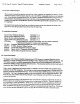
TOLE Type-II, Type-II+, Type-Ila Technical Manual 06/09/97 3:43 PM Page Purpose of this Document: This document is intended ta benefit the assembly line worker, repairman, est engineers and others by giving a derailed description of how the Type-1, Type-Ila, and Type-Ill TOLE transponders function, to the component level.
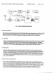
Page 6 of 39 06/09/97 3:43 PM Type-IL, Type-Ila, Type-II Technical Manual 4.8 Block Diagram: Following on the next page is the block diagram depicting the major functional areas of the and Type-I transponders.
TOLE Type-1, Type-II+, Type-III Technical Manual 06/09/97 3:43 PM Page 7 of 39 915 Mhz TX ed £3Y YMA. RF Amp Oscillator On/Off Battery Modulator AGITATION TOLE Controller | guppy pone TX Receive | pny © HE Switch Circuit { HELPER J Eig. I. Type-II Transponder Block Diagram 5.0 Modes of Operation: “The type-II tags can only operate in one of the four following modes, sleep, makeup, active, and time-out.
Page Time-Out Mode 06/09/97 3:43 PM Type-Ii, Type-II+, Type-II Technical Manual After the Transponder has successfully processed all of the data slot and activation commands, the TOLE transitions to a Time-Out Mode. During this mode the 32-Khz timer disables the 4 MHz oscillator, all data detection circuits, and any other unnecessary circuits. The length of the time-out is controlled by the reader (and is included in the RCM) and ranges from 0 to 30 seconds.
TOLE Type-1, Type-II+, Type-II Technical Manual 06/09/97 3:43 PM Page Detailed Operation: What follows is a detailed description of actual circuit operation down to the component level. The reference designation are those found on the appropriate schematic listed at the beginning of this document. And while this document references those designation, the schematic remains as the controlling document should an unforeseen discrepancy exist. 6.1 RF Board 6.1.
Page 10 of 39 06/09/97 3:43 PM Type-II, Type-I+, Typewrite Technical Manual ‘When in the receive mode the TUSCON signal (TOLE IC pin 27) is low leaving QS in its off state. Therefore the two diodes are without any forward bias and are thus off. Since they have very low junction capacitance very little 915 MHz energy leaks through them. Therefore the incident received RF energy is applied to the 50-ohm filterer Ul. When transmitting TUSCON is high which turns on QS.
TOLE Type-11, Typewrite, Type-III Technical Manual 06/09/97 3:43 PM Page 11 of 39 6.1.1.6 Detector Diode Bias Network The detector diode bias network consisting of R12 and R13 is used to forward bias the diode during receive mode. The steady-state voltage at TP9 is about 0.2V, the forward voltage of a Scottish diode. Notice that the cathode of the detector is sitting at DC ground. 6.1.1.
Page 12 of 39 06/09/97 3:43 PM Type-11, Type-II+, Type-LII Technical Manual 6.1.2.1 32 Khz Crystal The 32 Khz circuit consists of crystal Y2 and load capacitors C16 and C17. The input pin on the IC is pin 8 and the crystal drive pins pin 7, This circuit performs all the basic timing functions of the IC and tag. It times the sleep mode, the makeup interval, the LED flash rate and duty cycle, the beeper sounding rate and duty cycle and the sleep time-out period.
TOLE Type-I, Type-II+, Type-III Technical Manual 06/09/97 3:43 PM Page 13 of 39 The crystal startup time is specified in the TOLE spec as a maximum of § sec. 6.1.2.4 Current Reference The current reference pin is pin 12, Resistor R11 and decouple C51 are used to provide the proper bias current reference for the 32 Khz oscillator and input amplifier. A typical voltage to be expected at this pin is: Sleep mode: 55mV DC. Active mode: 55mv DC. 6.1.2.
Page 14 of 39 06/09/97 3:43 PM Type-II, Type-l+, Type-IT Technical Manual 6.1.2.9 TOLE IC Power Pins Pins BATAAN (pin 13), BATMEN (pin 15), and BATED (pin 25) supply the power to the various circuit blocks internal to the IC. Type-IL tags have these pins all tied to the battery. Capacitors C19, €22,C24, C26 provide a wide range of decoupling/filtering for these power pins. 6.1.2.
TOLE Type-II, Type-11+, Type-Eli Technical Manual 06/09/97 3:43 PM Page 15 of 39 The oscillator is comprised of transistors Q3 and Q4 (Siemens BF P-183), U2 (REM SAW, RP1094), and a few sundry bias/bypass components described below. U2 is a 2-port quartz Surface Acoustic Wave (SAW) integrated circuit resonator designed for resonance at 915 MHz. Q3 and Q4 provide enough gain to overcome the insertion loss of the resonator with enough left over to drive the downstream attenuation load.
Page 16 of 39 06/10/97 9:56 AM Type-I, Type-11+, Type-Ill Technical Manual Amplitude Shift Keying (ASK) modulation. The circuit elements that comprise this are Q1, R2,R3, C3, and C31. When DATABASE is high, transistor Q1 is cutoff thus Quest's collector is O volts. Therefore no RF signal is presented to the antenna. Likewise when DATABASE is low, Ql is biased into conduction via base divider R2 and R3, QI conducts providing +3V power to the collector of Ql.
TOLE Type-IL, Type-1+, Type-II Technical Manual 06/09/97 3:43 PM Page 17 of 39 The beeper can be in an off , confirmation, or warning mode. The off mode is self-explanatory. The beeper confirmation tone is an intermittent pulsed 4096-Hz tone with a total duration sec. This tone consists of four chirp tones. Each chirp tone shall have a period of 0.5 seconds and a duty cycle of 50%. The warning or “negative confirmation” tone is a continuous 4096-Hz tone with a total duration seconds, 7.
Page 18 of 39 06/09/97 3:43 PM Type-IL, Type-II+, Type-HI Technical Manual 7.1 Common Symptoms: Tag does not wake up: This symptom is confirmed by the amount of current the tag draws, When in the sleep mode it draws about 15 uA. When in the acquisition mode it draws perhaps 100 to 150 uA and when fully awake and talking to the reader it draws about the average. The tag does not transmit any signal in the sleep or acquisition modes.
TOLE Type-II, Type-II+, Type-Ill Technical Manual 06/10/97 9:56 AM Monitoring instrument giving erroneous reading Check all cables, interconnects, couplets, etc., between monitoring point and instrument. Incorrect circuit component(s} in receive path Replace all components in receive path taking care to determine which component is at fault. This problem could occur again if a machine is set up with the wrong part or if a vendor shipped the wrong part, etc.
Page 20 of 39 06/10/97 9:56 AM Type-11, Typewrite, Type-lii Technical Manual Bad IC Replace U3 Bad solder joint or solder bridge somewhere in circuit Visually inspect all alder joints for good flow and shiny surface under well-lit high power magnifying glass.
TOLE Type-11, Teletype, Type-III Technical Manual Tag transmit power weak: 06/10/97 9:56 AM Page 2] of 39 Low battery voltage Check battery voltage-should Battery statically OK but dips low when transmitter on Check battery voltage under a 50-ohm Joan, should not drop less than about 2.4V TX/RX switch not functioning properly Check to make sure diodes CR1 and CR2 have proper forward bias (0.
Page 22 of 39 06/10/97 9:56 AM Type-11, Type-Ii+, Type-HI Technical Manual Blown LED Replace LED Bad switch transistor Replace faulty Q9, Q10, or Q11, depending on which circuit is faulty. LED in backwards Check orientation per assembly print LED not being commanded on by IC Other circuit blocks are potentially at fault Identify other symptoms and continue to better diagnose the problem. Shorted TOLE IC output pins Inspect board for solder bridges, splashes, etc. Faulty IX-replace it.
TOLE Type-11, Type-II+, Type-III Technical Manual 06/10/97 9:56 AM Incorrect component or incorrect component Visually compare components’ size and color value against known good unit Cracked or broken component Check all components under a lighted high- power magnifying slaps Tag battery drains quickly: Tag continuously transmitting Check TX/RX circuit to make sure tag is not stuck in CW (continuous wave) transmit mode.
Page 24 of 39 06/10/97 9:56 AM Type-11, Type-Ila, Type-II Technical Manual 7.2 Typical Voltages: The following table gives some typical values that can be expected in a working system. These values are not intended to reflect actual manufacturing test limits but are given instead to help the repair person diagnose a faulty tag.
TOLE Type-IL, Type-Ila, Type-TI Technical Manual 06/10/97 9:56 AM Page base modulator Shape similar to ROUNDABOUT but voltage fluctuates between 2.2. and 3.0v Q5 collector T/R switch driver Q.15V typical, range is 0.0 to 0.2V Q1 collector modulator Should Nook like an inverted DATABASE signal with slightly less voltage peak (VAT 0.2V or 50) Q3 collector oscillator output Looks like Q1 collector as the 915 Mhz component is not visible with an oscilloscope.
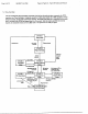
Page 26 of 39 06/09/97 3:43 PM Type-H, Type-II+, Type-III Technical Manual 915 Mhz Amp [20 container On/Off +— Battery Recall Modulator Soc matador] TOLE 1 Controller TX/RX Receive | pony ran ic BE Micro Switch Circuit a BEEPER Driver Interface ig. 3. Type-Tl+ Block Diagram for Type-IL+ Transponder Shown above is the block diagram depicting the major functional areas of the Type-Ila transponder. Note the addition of the microprocessor between the TOLE IC and the driver interface.
TOLE Type-I, Type-II+, Type-HI Technical Manual 06/09/97 3:43 PM Page Typical Voltages for Type-Ila Transponder: The following table gives some typical values that can be expected in a working system. These values are not intended to reflect actual manufacturing test limits but are given instead to help the repair person diagnose a faulty tag.
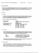
Page 28 of 39 06/09/97 3:43 PM Type-11, Type-Ila, Type-Ill Technical Manual Type-III Transponder 915 Mhz, = f——ishz Amp Oscillator On/Off — +3V and +5V Power Digital Brd. ty Interface Modulator —— = TOLE [Sm mat Serial Controller [pe Interface Ic TX/RX RED : . Filter Detector SHERATAN YELL, Driver Switch EER ace r 12-pin Header Dig. Brd. Interface RF Board P BAT +3V + BAT wore Kn Cod. ny Parr 43V and 4+5V Switch Power I RF Brd. ce Interface 20 Mhz Micro controller MUSCLE.
TOLE Type-11, Teletype, Type-HI Technical Manual 06/09/97 3:43 PM Page Block Diagram for Type-Ila Transponder Shown above is the block diagram depicting the major functional areas of the Type-II transponder. The driver signaling has been moved from the RF board to the digital board where, like in the Teletype case, the micro has been given control over driver signaling. In this way the micro can be programmed for any variety of driver signaling that is desired.
TOLE Type-I, Type-H+, Type-III Technical Manual 06/09/97 3:43 PM Page 31 of 39 Digital Board | U4-P1, -P2 regulator output S.0V SV regulator U4-p3, -P4 ground av Ur-PS low voltage detect 5V U4-ps, p7 voltage adjustment 1.28v pins Digital Board | U3-P31 micro’s input pin 2.2VDC level with 2.6Vpp sine wave Micro. from resonator riding on top resonator U3-p32 micro’s output pinto | 2.3VDC level with 3.
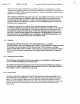
TOLE Type-11, Type-II+, Type-Ill Technical Manual 06/09/97 1:02 PM Page 33 of 39 cursor Position ony 1 swoon Worms 10.3 Fig 5. TOLE IC Pin 14, Detector Diode Bias Waveform During “Sniff Mode™ b= dona? HER SIRE OFF Parameters 20 ps | PALL ind: 3.00 % Se FU DUS UU FO Tine ” SIRE Twos 0 wii 10.4 Fig 6.
Page 34 of 39 06/09/97 1:02 PM Type-1, Type-II+, Type-Ill Technical Manual ‘ Lod? TRACEABLE STUFF Condign A | Los [7] | am snr Ios FRET ; 5 lope ] ! | Fos y uu Ud Jey Squidgy 1 Window holdall—
TOLE Type-II, Type-Ii+, Type-HI Technical Manual 06/09/97 1:02 PM Page 35 of 39 PREFIGURE ] i Cp bos Tie's! Zev 103 MSs. Tov ong I 1 00 ind Bu v Provocative 0 torrent 10.7 Fig 9. TOLE IC Pin 4, MHz Crystal Output Waveform 97 MEASURE fern fo or l L
Page 36 of 39 06/09/97 1:02 PM Type-II, Type-H+, Typewrite Technical Manual Foi gainer one TRI 4 : Estes Lone Ling 2 AC LURES HERE HF slap 2 Pas 41 Window 7 2 [holder fF ops Tire tuts 168 15's 300 equine $v oo oO NORMAL 10.9 Fig 11. TOLE IC Pin 10, BRATTAIN Waveform with Weak Signal TRIGGER SETUP SHEET A134 ect Extol Line trigger an Laue FRET HF isotope 2 Pos om hed IF Fry Time Lube 9 NINES 0 HIRAM 10.10 Fig 12.