(Model TS350) PART NO. A05728 - 08-26-05 - Rev. A Copyright © 2005 Delta Machinery To learn more about DELTA MACHINERY visit our website at: www.deltamachinery.com. For Parts, Service, Warranty or other Assistance, ESPAÑOL: PÁGINA 29 please call 1-800-223-7278 (In Canada call 1-800-463-3582).
TABLE OF CONTENTS IMPORTANT SAFETY INSTRUCTIONS . . . . . . . . . . . . . . . . . . . . . . . . . . . . . . . . . . . . . . . . . . . . . . . . . . . . . . . . . . . . 2 SAFETY GUIDELINES - DEFINITIONS. . . . . . . . . . . . . . . . . . . . . . . . . . . . . . . . . . . . . . . . . . . . . . . . . . . . . . . . . . . . . 3 GENERAL SAFETY RULES . . . . . . . . . . . . . . . . . . . . . . . . . . . . . . . . . . . . . . . . . . . . . . . . . . . . . . . . . . . . . . . . . . . . .
SAFETY GUIDELINES - DEFINITIONS It is important for you to read and understand this manual. The information it contains relates to protecting YOUR SAFETY and PREVENTING PROBLEMS. The symbols below are used to help you recognize this information. Indicates an imminently hazardous situation which, if not avoided, will result in death or serious injury. Indicates a potentially hazardous situation which, if not avoided, could result in death or serious injury.
GENERAL SAFETY RULES READ AND UNDERSTAND ALL WARNINGS AND OPERATING INSTRUCTIONS BEFORE USING THIS EQUIPMENT. Failure to follow all instructions listed below, may result in electric shock, fire, and/or serious personal injury or property damage. IMPORTANT SAFETY INSTRUCTIONS 1. FOR YOUR OWN SAFETY, READ THE INSTRUCTION MANUAL BEFORE OPERATING THE MACHINE. Learning the machine’s application, limitations, and specific hazards will greatly minimize the possibility of accidents and injury. 2.
ADDITIONAL SPECIFIC SAFETY RULES FAILURE TO FOLLOW THESE RULES MAY RESULT IN SERIOUS PERSONAL INJURY. 1. DO NOT OPERATE THIS MACHINE until it is assembled and installed according to the instructions. 2. OBTAIN ADVICE FROM YOUR SUPERVISOR, instructor, or another qualified person if you are not familiar with the operation of this machine. 3. FOLLOW ALL WIRING CODES and recommended electrical connections. 4. USE THE GUARDS WHENEVER POSSIBLE.
POWER CONNECTIONS A separate electrical circuit should be used for your machines. This circuit should not be less than #12 wire and should be protected with a 20 Amp time lag fuse. If an extension cord is used, use only 3-wire extension cords which have 3-prong grounding type plugs and matching receptacle which will accept the machine’s plug.
EXTENSION CORDS MINIMUM GAUGE EXTENSION CORD RECOMMENDED SIZES FOR USE WITH STATIONARY ELECTRIC MACHINES Ampere Rating 0-6 0-6 0-6 0-6 6-10 6-10 6-10 6-10 10-12 10-12 10-12 10-12 12-16 12-16 12-16 Use proper extension cords. Make sure your extension cord is in good condition and is a 3wire extension cord which has a 3-prong grounding type plug and matching receptacle which will accept the machine’s plug. When using an extension cord, be sure to use one heavy enough to carry the current of the machine.
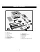
CARTON CONTENTS 1 2 3 15 4 14 11 5 13 12 6 10 Fig. A 7 9 8 1. 2. 3. 4. 5. 6. 7. 8. Table Saw Extension Wing (2) Rip Fence Miter Gauge Rip Fence Handle Handwheel Lock Knob (2) M10 Flat Washer (2) Handwheel (2) 9. 10. 11. 12. 13. 14. 15.
2 1 8 9 333 6 13 7 5 4 16 15 18 20 22 12 14 11 10 17 21 19 Fig. B For Blade Guard and Splitter Assembly 1. Splitter Bracket 2. 5/8" Flat Washer (2) 3. M12 x 1.75 Hex Nut (2) 4. M6 x 1x20mm Hex Head Screw 5. 1/4" External. Tooth Lockwasher (2) 6. 5/16" Flat Washer (2) 7. M6 x 1 Wing Nut 8. 13mm Open End Wrench 9. 15/16" Hex Arbor Wrench For Fastening Saw to Stand 14. M8 x 1.25 x 16mm Hex Head Screws (4) 15. 3/8" Flat Washer (8) 16. M8 x 1.25 Hex Nut (4) For Rear Guide Rail 17. M8 x 1.
DUST COLLECTION CONNECTOR 1 2 3 Do not operate this machine without the dust collection connector mounted. 1. 2. 3. 4. - Adapter Plate Dust Collection Hood Adapter Plate #10x1/2" Sheet Metal Screws (4) 2 Fig. D 4 ASSEMBLY For your own safety, do not connect the machine to the power source until the machine is completely assembled and you read and understand the entire instruction manual.
DUST COLLECTION CONNECTOR Do not operate the machine without the dust collector attached. The TS350 is supplied with a dust collection connector to provide a means of connecting a 4" diameter dust collection hose to the machine. A D C Fig. 3 Fig. 4 1. Turn the saw table face down on a piece of cardboard to protect the table surface. Align the four holes in the saw cabinet with the four holes (A) Fig. 5A in the stand. 2. Align the two holes (A) Fig.
ATTACHING THE SAW TO THE STAND. 1. Turn the saw table face down on cardboard to protect the table surface. Align the four holes in the saw cabinet with the four holes in the stand. 2. Place a 3/8" flat washer on an M8 x 1.25 x 16mm hex head screw. Insert the screw through the hole in the stand and the hole in the saw. Place a 3/8" flat washer on the screw. Thread an M8 x 1.25 hex nut on the screw. Tighten securely. Repeat this process for the three remaining holes. 3. Turn saw table face up (Fig. 8). 4.
2. Use a straight-edge (C) Fig. 12 to see if the extension wing (A) is level with the saw table (D) before tightening the three screws (B) Fig. 11. C D 3. Attach the other extension wing to the opposite side of the table in the same manner. A Fig. 12 SAW BLADE Disconnect the machine from the power source! NOTE: Two wrenches are supplied - a box-end and an open-end. NOTE: Use only 10" saw blades with 5/8" arbor holes that are rated for 3000 RPM or higher 1.
D C E F H G A A B Fig. 17 Fig. 16 K D F E G H M J L Fig. 18 Fig. 19 P X B C V D A D E P E Fig. 20 W T C S Fig.
ATTACHING THE GUIDE RAILS 1. Align the three slotted holes in the front right guide rail (A) Fig. 16, with two holes (B) in saw table and slotted hole (C) in extension wing. Insert a M6 x 1 x 20mm carriage head screw (D) Fig. 14, through the three holes in the front right guide rail, and the saw table. Place a M6.4 flat washer (E), and a 6.1 lockwasher (F) onto the carriage head screw (D). Thread an M6 x 1 hex nut (G) onto the carriage head screw (D) and hand tighten only.
LEVELING AND ADJUSTING THE FRONT GUIDE RAIL Disconnect the machine from the power source! 1. Raise the saw blade to its highest level. 2. With the fence handle (A) Fig. 24 in the raised position, place the rip fence (B) on the saw table. NOTE: Make certain that the rip fence (B) is engaged on the rear guide rail (C). Move the rip fence (B) against the saw blade (Fig. 25). 3. Carefully move the front guide rail (D) Fig.
6. Align the hole in the blade guard and splitter assembly (E) Fig. 29 with the hole in the splitter bracket (C). NOTE: Make certain that the two protrusions (pins)(G) Fig. 30 are engaged with the channel of the splitter assembly. 7. Place a 1/4" external tooth lockwasher and a 5/16" lockwasher on an M6 x 1 x 20mm hex head screw. Insert the hex head screw (D) Fig. 29 through the hole in the support bracket, then through the slot in the blade guard/splitter assembly. 8.
FASTENING THE STAND TO A SUPPORTING SURFACE If the saw has a tendency to tip over, slide, or walk on the supporting surface, secure the saw stand to the floor. A The rubber feet (A) Fig. 34 have holes that allow you to mount the saw stand to the floor without removing the saw from the stand. Fig. 34 OPERATION OPERATIONAL CONTROLS AND ADJUSTMENTS STARTING AND STOPPING THE SAW The switch (A) is located on the front panel of the saw cabinet, as shown in Fig. 35.
ADJUSTING THE 90° AND 45° POSITIVE STOPS Disconnect the machine from the power source! Your saw is equipped with positive stops that will rapidly position the blade at 90° and 45° to the table. To check and adjust the positive stops: 1. Turn the handwheel that tilts the blade clockwise as far as it will go. Make sure that the table insert is level with the table. Place a square (A) Fig. 38 on the table against the blade. See if the blade is 90° to the table. If not, then loosen the set screws (B) Fig.
H 3. The witness line (F) Fig. 43, located on the cursor (G), shows the distance from the fence to the blade. To adjust the cursor (G), make a test cut with the fence locked in position. Measure the width of your finished cut. Loosen the two screws (H), and adjust the cursor (G) until the witness line (F) is aligned with the same marking on the scale (K) as the finished cut. Tighten the two screws (H). F Fig. 43 G K MITER GAUGE OPERATION AND ADJUSTMENTS 1.
MACHINE USE Common sawing operations include ripping and crosscutting. As with all power machines, a certain amount of danger is involved with the operation and use of the machine. Using the machine with the respect and caution will considerably lessen the possibility of personal injury. However, if normal safety precautions are overlooked or completely ignored, personal injury can result. The following information describes the safe and proper method for performing the most common sawing operations.
RIPPING Ripping is the operation of making a lengthwise cut through a board (Fig. 51) Use the rip fence (A) to position and guide the work. Place the workpiece so that one edge rides against the rip fence while the flat side of the board rests on the table. Since the work is pushed along the fence, it must have a straight edge and make solid contact with the table. Use the saw guard.
USING THE ACCESSORY DADO HEAD Do not use a dado blade larger than 6" in diameter. Dadoing is cutting a rabbet or wide groove into the workpiece. Most dado head sets are made up of two outside saws and four or five inside cutters (Fig. 58). Various combinations of saws and cutters are used to cut grooves from 1/8" to 13/16" for use in shelving, making joints, tenoning, grooving, etc. Fig.
STORING THE RIP FENCE You can store the rip fence (B) Fig. 63 on the holder bracket. B Fig. 63 STORING THE MITER GAUGE AND WRENCH The two holder brackets hold the miter gauge (C) and and the blade changing wrenches (D) Fig. 64. D A Fig.
1/2" SQUARES CUT OFF HERE TO PUSH 1/2" WOOD CUT OFF HERE TO PUSH 1/4" WOOD NOTCH TO HELP PREVENT HAND FROM SLIPPING MAKE FROM 1/2" OR 3/4" WOOD OR THICKNESS LESS THAN WIDTH OF MAT’L. TO BE CUT PUSH STICK CONSTRUCTING A PUSH STICK When ripping work less than 4 inches wide, use a push stick to complete the feed. Make this push stick from scrap material using the following pattern.
TROUBLESHOOTING For assistance with your machine, visit our website at www.deltamachinery.com for a list of service centers or call the DELTA Machinery help line at 1-800-223-7278 (In Canada call 1-800-463-3582). MAINTENANCE KEEP MACHINE CLEAN LUBRICATION Periodically blow out all air passages with dry compressed air. All plastic parts should be cleaned with a soft damp cloth. NEVER use solvents to clean plastic parts. They could possibly dissolve or otherwise damage the material.
ACCESSORIES A complete line of accessories is available from your Delta Supplier, Porter-Cable • Delta Factory Service Centers, and Delta Authorized Service Stations. Please visit our Web Site www.deltamachinery.com for a catalog or for the name of your nearest supplier. Since accessories other than those offered by Delta have not been tested with this product, use of such accessories could be hazardous. For safest operation, only Delta recommended accessories should be used with this product.
WARRANTY To register your tool for warranty service visit our website at www.deltamachinery.com.