VENTILATION FAN / LED LIGHT MODELS 150F/150LEDNL/150LED-ADJ/150DS TABLE OF CONTENTS 150F/150DS Package Contents 2 General Safety Information 3 Preparation and Wiring Diagrams 4 Assembly Instructions - New Construction 5 Assembly Instructions - Existing Construction 6 Grille Installation 10 Care and Maintenance 11 Troubleshooting 12 Dimensions 13 Product Specifications 13 Warranty 14 150LEDNL/150LED-ADJ READ AND SAVE THESE INSTRUCTIONS Address: 46101 Fremont Boulevard, Fremont, CA 9
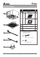
PACKAGE CONTENTS PART DESCRIPTION QTY 1 Fan Body 1 1 150F / 150DS 1 2 Grille 150LEDNL / 150LED-ADJ 1 2 3 Hanger Bar Ⅰ 13”(318.5mm) 2 4 Hanger Bar Ⅱ 13”(318.5mm) 2 5 Duct Connector 1 HARDWARE CONTENTS (Images are to scale) 3 A ×4 Tapping Screw ( ø 4 x 25mm) 4 B ×4 Screw (#8-32 x 1/4 in.
GENERAL SAFETY INFORMATION READ AND SAVE THESE INSTRUCTIONS GENERAL SAFETY INFORMATION 7. If this unit is to be installed over a tub or shower, it must be marked as appropriate for the application and be connected to a GFCI (Ground Fault Circuit lnterrupter) – protected branch circuit. 1. Make sure that the electric service supply voltage is AC 120V, 60Hz. 8. Do not use this unit with any other solid-state control device.
PREPARATION Tools Required for Assembly (not included): Hammer, Flathead Screwdriver, Wire Nuts, Nails, Duct Tape, Phillips Head Screwdriver, Utility Knife Helpful Tools (not included): Electric Drill, Drill Bits Proper insulation around the fan to minimize building heat loss and gain. 6 in. circular duct is recommended for installation. The ducting from this fan to the outside of building has a strong effect on air flow, noise and energy use of the fan.
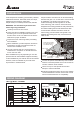
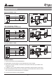
YELLOW YELLOW WHITE WHITE WHITE RED RED RED WHITE WHITE WHITE GREEN OFF ON OFF ON NIGHT-LIGHT SWITCH NIGHT-LIGHT SWITCH ON OFF NIGHT-LIGHT SWITCH OFF ON OFF LIGHTON SWITCH LIGHTON SWITCH LIGHT SWITCH GREEN GREEN WIRING DIAGRAM Single Speed Model: 150F Single Speed Model: 150F Single Speed Model: 150F Single Speed Model: 150F JUNCTION BOX JUNCTION BOX JUNCTION BOX BLACK BLACK WHITE BLACK WHITE WHITE GREEN GREEN LN L N L N N L L N L N N GRD GRD GRD ON/OFF SWITCH (purchase ON/OFF separately) SWITCH (p
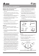
ASSEMBLY INSTRUCTIONS Attach duct connector Note: Remove the tape from the damper before installation. C 1. Attach the duct connector from outside, and secure by using one screw (#8-32 x 1/4 in.). (Fig. C). Insert tab into hole in housing Insert tab into the gap between fan unit and housing Screw D 2. Remove the motor assembly, attach the duct connector from the housing can inside, and secure by using one screw (#8-32 x 1/4 in.). Insert and secure motor assembly. (Fig. D).
ASSEMBLY INSTRUCTIONS G 4. Ensure that the distance between the ceiling and fan body is appropriate for mounting the grille. Tab 5. Secure the suspension brackets to the joists with nails or by using the tapping screws (Ø4x25mm) through holes near nails. Joist 6. Secure the suspension bracket to the fan body using the screws (#8-32 x 1/4 in.). 7. Follow steps 2 to 6 of the installation instructions to complete the installation work H Install the housing (II)-using mounting tabs 1.
GRILLE INSTALLATION For 150F/150DS Slots 1. With the power on, check for abnormal vibrations or sounds. Spring 2. Insert mounting springs into the slots and mount the grille to the fan body For 150LEDNL Slots Celling 1. Insert the LED light connector into the LED socket 2. With the power on, check for abnormal vibrations or sounds. Spring 3. Insert mounting springs into the slots and mount the grille to the fan body LED light connector For 150LED-ADJ Grille Grille 1.
OPERATION Turn the switchs on/off to operate the fan / light / night light. Dual Speed Model: 150DS 1. Low speed control mode: Turn the POWER switch on (MODE switch is off) to operate at the useradjustable low speed air flow - the LED indicator will be green. Delay time control (150DS) 2. Full speed control mode: Turn the POWER switch & MODE switch on to operate at full speed mode - the LED indicator will be amber.
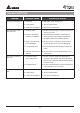
TROUBLESHOOTING PROBLEM The fan is not turning on The fan seems louder than it should The fan is not clearing the room The light is not turning ON POSSIBLE CAUSE CORRECTIVE ACTION 1. Power off 1. Make sure power supply is on. 2. Faulty switch 2. Test or replace switch. 3. Faulty wire connection 3. Check wire in switch box. 1. CFM too great 1. Be sure the CFM rating on the fan matches the size of your room. 2. Damper not working properly or damaged 2.
DIMENSIONS 150F/150DS 6" (150) 14 (35 " 6) 7 11/16" (195) 10 1 (26 /2" 7) " 14 6) (35 150LEDNL / 150LED-ADJ " 3/8 11 89) (2 14" ) 6 (35 14 (35 " 6) Unit: Inches (mm) PRODUCT SPECIFICATIONS Model No. Voltage Frequency Air Flow @ 0.1"SP Power @ 0.1"SP Max. Power Weight (V) (Hz) (CFM) (W) (Watt) (lb.) Note Light Spec 150F/ VFB150E6A1 120 60 150 16.9 30 10.4 Single Speed 150LEDNL/ VFB150E6LED1 120 60 150 17.6 50 10.
WARRANTY DELTA ELECTRONICS THREE YEAR LIMITED WARRANTY Delta Electronics Inc. (“Delta Electronics”) warrants to the original consumer purchaser in the USA that the Breez ventilation fan products will be free from defects in material or workmanship. This warranty is limited to three (3) years from the original date of purchase. Limitations and Exclusions 1. During the warranty period, a replacement for any defective product will be supplied free of charge for installation by the consumer.