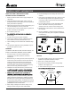
VENTILATION FAN MODEL 50F / 70F / 70HS TABLE OF CONTENTS Package Contents 2 General Safety Information 3 Preparation and Wiring Diagrams 4 Assembly Instructions - New Construction 5 Assembly Instructions - Existing Construction 6 Grille Installation 8 Humidity Sensing Fan Operation 8 Single Speed Fan Operation 8 Care and Maintenance 9 Troubleshooting 10 Dimensions 11 11 Warranty READ AND SAVE THESE INSTRUCTIONS Address: 46101 Fremont Boulevard, Fremont, CA 94538 US Toll Free Number:
PACKAGE CONTENTS 2
GENERAL SAFETY INFORMATION READ AND SAVE THESE INSTRUCTIONS GENERAL SAFETY INFORMATION 6. Ducted ventilating fans must always be vented to the outdoors. 1. Make sure that the electric service supply voltage is AC 120V, 60Hz. 7. If this unit is to be installed over a tub or shower, it must be marked as appropriate for the application and be connected to a GFCI (Ground Fault Circuit lnterrupter) – protected branch circuit. 2.
PREPARATION Tools Required for Assembly (not included): Hammer, Flathead Screwdriver, Wire Nuts, Nails, Duct Tape, Phillips Head Screwdriver, Utility Knife Short piece of flexible duct helps alignment and absorbs sound Helpful Tools (not included): Electric Drill, Drill Bits Fan housing WARNING: Turn off electricity at breaker box before beginning installation. or Carefully remove unit from carton.
ASSEMBLY INSTRUCTIONS NEW CONSTRUCTION BEFORE INSTALLATION Turn off power source. Review all safety precautions. 1. Attach the Duct Connector 1 to the Fan Body ❶ . ❶ 2. Remove the wiring box cover from the Fan Body ❶ . Remove the wiring knockout from the wiring box cover with a flathead screwdriver (not included). 2 ❶ 3. Place the Fan Body ❶ next to a ceiling joist or wall stud. The Fan Body ❶ should be level and perpendicular to the joust or stud. 3 ❶ 4.
ASSEMBLY INSTRUCTIONS 5.Pull the wire through the hole and into the junction box(not included), secure 120VAC house wiring from the wall diagram on page4. 14AWG is the smallest conductor that shall be used for branch-circuit wiring. 5 ❶ Push the wires back through the hole. Reattach the wiring box cover. 6 6 6. Install a circular 3 in. duct (not included) and secure it with duct tape or clamps (neither included). 3 in. Duct Finish ceiling work.
ASSEMBLY INSTRUCTIONS 3 3. If this fan is not replacing an old fan, be sure to cut a 7 1/2in. x 7 1/4in. opening for the Fan Body ❶ . Make sure the 7 1/4 inch side of opening is flush with the joist for installation from below. in. 7 1/2 " 9.4 .4" 9/4 71 in. 4 4. Attach the Duct Connector to the Fan body. Remove the wiring box cover from the Fan Body ❶ . Remove the wiring knockout from the wiring box cover with a flathead screwdriver (not included).
GRILLE INSTALLATION 1 1. Pinch the mounting springs on the Grille , and insert them into the narrow rectangular slots inside the fan. Push the Grille up toward the ceiling. Turn on electricity at the breaker box after finishing installation. HUMIDITY SENSING FAN OPERATION Model: 70HS 1 1. Humidity Sensing Mode: Flip wall switch to “ON” position. The LED indicator light in the fan will be BLUE. The fan will automatically start when the humidity level in the room is above 60%.
CARE AND MAINTENANCE See safety information before proceeding. Routine maintenance should be done at least once a year. • Never use solvents, thinner or harsh chemicals when cleaning the fan. • Do not allow water to enter the motor. 1 • Do not immerse metal parts in water. • Do not immerse resin parts in water over 140º Fahrenheit. Turn off power source. Review all safety precautions. 1. To remove grille ❷ , squeeze springs and pull down. 2 2. Wash and clean the grille ❷ in a sink and dry with a cloth.
TROUBLESHOOTING PROBLEM The fan is not turning on The fan seems louder than it should POSSIBLE CAUSE CORRECTIVE ACTION 1. Power off 1. Make sure power supply is on. 2. Faulty switch 2. Test or replace switch. 3. Faulty wire connection 3. Check wire in switch box. 1. CFM too great 1. Be sure the CFM rating on the fan matches the size of your room. 2. Damper not working properly or damaged 2. Check damper to ensure it is opening and closing properly.
DIMENSIONS 9 3/8 3 10 3/4 4 13/16 UNIT: INCH PRODUCT SPECIFICATIONS Voltage (V) Frequency (Hz) Air Flow @0.1"SP (CFM) Power @ 0.1"SP (W) Max Current (Amps) Weight (lb.) Note 70HS / VFB070B3H1 120 60 70 13.2 0.29 3.65 Humidity Sensing 70F / VFB070B3A1 120 60 70 13.2 0.29 3.65 Single Speed 50F / VFB050B3A1 120 60 50 6.4 0.18 3.65 Single Speed Model No.
WARRANTY DELTA ELECTRONICS THREE YEAR LIMITED WARRANTY Delta Electronics Inc. (“Delta Electronics”) warrants to the original consumer purchaser in the USA and Canada that the Breez ventilation fan products will be free from defects in material or workmanship. This warranty is limited to three (3) years from the original date of purchase. Limitations and Exclusions 1. During the warranty period, a replacement for any defective product will be supplied free of charge for installation by the consumer.