VENTILATION FAN / LED LIGHT MODELS 80RLED-ADJ / ITG80RLED TABLE OF CONTENTS Package Contents 2 General Safety Information 3 Preparation and Wiring Diagrams 4 Assembly Instructions - New Construction 5 Assembly Instructions - Existing Construction 6 Grille Installation 8 Care and Maintenance 9 Troubleshooting 10 Dimensions 11 Product Specifications 11 Warranty 12 READ AND SAVE THESE INSTRUCTIONS Address: 46101 Fremont Boulevard, Fremont, CA 94538 US Toll Free Number: 1-888-979-9889 – T
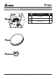
PACKAGE CONTENTS 1 2 3 2 PART DESCRIPTION QTY 1 Fan Body 1 2 Grille 1 3 Duct Connector 1
GENERAL SAFETY INFORMATION READ AND SAVE THESE INSTRUCTIONS GENERAL SAFETY INFORMATION 7. If this unit is to be installed over a tub or shower, it must be marked as appropriate for the application and be connected to a GFCI (Ground Fault Circuit lnterrupter) – protected branch circuit. 1. Make sure that the electric service supply voltage is AC 120V, 60Hz. 8. Do not use this unit with any other solid-state control device.
PREPARATION Tools Required for Assembly (not included): Hammer, Flathead Screwdriver, Wire Nuts, Nails, Duct Tape, Phillips Head Screwdriver, Utility Knife Helpful Tools (not included): Electric Drill, Drill Bits Proper insulation around the fan to minimize building heat loss and gain. 4” circular duct is recommended for installation. The ducting from this fan to the outside of building has a strong effect on air flow, noise and energy use of the fan.
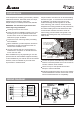
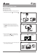
ASSEMBLY INSTRUCTIONS NEW CONSTRUCTION BEFORE INSTALLATION Turn off power source. Review all safety precautions. 1. Attach the Duct Connector 3 to the Fan Body 1 1 . 3 1 2 2. Remove the wiring box cover from the Fan Body 1 . Remove the wiring knockout from the wiring box cover with a flathead screwdriver (not included). 1 3 3. Place the Fan Body 1 next to a ceiling joist or wall stud. The Fan Body 1 should be level and perpendicular to the joust or stud. 4.
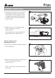
ASSEMBLY INSTRUCTIONS 5 5. Remove the fan junction box cover. Using wire nut(not supplied), connect house wires to fan wires as shown in the wiring diagram on page 4. 14AWG is the smallest conductor that shall be used for branch circuit wiring. Reattach fan junction box cover. wire nut (not included) House wires Product wires 6 6. Install a circular 4 in. duct (not included) and secure it with duct tape or clamps (neither included). 4 in. Duct Finish ceiling work.
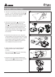
ASSEMBLY INSTRUCTIONS 3 3. If this fan is not replacing an old fan, be sure to cut a 7 1/2in. x 7 1/4in. opening for the Fan Body 1 . Make sure the 7 1/4 inch side of opening is flush with the joist for installation from below. ". 9.4in 7 1/2 71 in. /94.4" 4 4. Attach the Duct Connector 3 to the Fan body. Remove the wiring box cover from the Fan Body 1 . Remove the wiring knockout from the wiring box cover with a flathead screwdriver (not included).
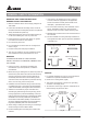
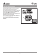
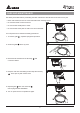
GRILLE INSTALLATION For the LED light connection, plug in the connector from the grille into the fan housing as shown. Pinch the mounting springs on the Grille 2 , and insert them into the narrow rectangular slots inside the fan. Push the Grille 2 up toward the ceiling. Using the switch on the back of grille, choose the color temperature you want for your LED. You can choose from 2700K warm white, 4000K cool white, and 5000K daylight white.
CARE AND MAINTENANCE See safety information before proceeding. Routine maintenance should be done at least once a year. • Never use solvents, thinner or harsh chemicals when cleaning the fan. 1 • Do not allow water to enter the motor. • Do not immerse metal parts in water. • Do not immerse resin parts in water over 140º Fahrenheit. Turn off power source. Review all safety precautions. 1. To remove grille 2. Clean the grille 2 2 , squeeze springs and pull down. 2 2 with a dry cloth. 3.
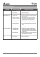
TROUBLESHOOTING PROBLEM The fan is not turning on The fan seems louder than it should The fan is not clearing the room The light is not turning ON POSSIBLE CAUSE CORRECTIVE ACTION 1. Power off 1. Make sure power supply is on. 2. Faulty switch 2. Test or replace switch. 3. Faulty wire connection 3. Check wire in switch box. 1. CFM too great 1. Be sure the CFM rating on the fan matches the size of your room. 2. Damper not working properly or damaged 2.
DIMENSIONS 7-1/2"(195) 1-1/2"(40) 0) 30 1"( 1 ø 4" (100) 5-3/4"(146) 9-1/2"(240) Unit: Inches (mm) PRODUCT SPECIFICATIONS Model No. 80RLED-ADJ/ ITG80RLED/ VFB080B4RLED1 Voltage Frequency Air Flow @ 0.1"SP Power @ 0.1"SP Max Current Weight (V) (Hz) (CFM) (W) (Amps) (lb.) 120 60 80 11.5 Note: Design and specifications subject to change without notice. 11 0.28 7.
WARRANTY DELTA ELECTRONICS THREE YEAR LIMITED WARRANTY Delta Electronics Inc. (“Delta Electronics”) warrants to the original consumer purchaser in the USA that the Breez ventilation fan products will be free from defects in material or workmanship. This warranty is limited to three (3) years from the original date of purchase. Limitations and Exclusions 1. During the warranty period, a replacement for any defective product will be supplied free of charge for installation by the consumer.