
Combustible Ceiling Installation Instructions

Ceilin
Information is subject to change without notice or obligation. M-54738 Rev. C
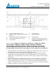
Notes: Dimensions denoted by ( ) are in millimeters.
Ceiling Radiation Damper
GBR-CRD
Combustible Ceiling Installation Instructions
A
-
Gypsum (Thickness may vary)
F
-
Finish Flooring
B
-
Resilient Channel (Refer to Floor/Ceiling
Design)
G
-
Damper Supports
C
-
Wood Joist/Wood Truss (Minimum 18”)
H
-
Support Braces
D
-
Sub-Flooring (Thickness may vary)
I
-
Picture Frame and Grille Location
E
-
Vapor Barrier
J
-
Delta Breez GBR-CRD Damper and
GreenBuilder/Elite Fan
For fan models: VFB050C4L1, VFB050C4A1, VFB080C4L1, VFB080C4A1, GBR50L,
GBR50, GBR80L, GBR80LED, GBR80, GBR80H, GBR80HL, GBR80MHL,
GBR80MHLED, GBR80HLED, GBR100L, GBR100H, GBR100HL, GBR100MHL,
GBR100, GBR100LED, GBR100HLED, ELT80-110, ELT80-110LED, ELT80-110D,
ELT80-110DLED, ELT80-110H, ELT80-110HLED, ELT80-110MH, ELT80-110MHLED.
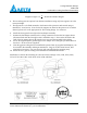
1. Install the damper to the ventilation fan. The damper sleeve should align with four holes on
the fan housing. Secure the sleeve using the supplied #12 screws.
2. For a damper used with a fan equipped with a grille light, route the wire from the grille
through the notch on the damper frame. Use the supplied bracket to secure the wire to the
damper frame. Attach the bracket to the frame as seen in Figure 3 using one of the supplied
#8-18 screws.
3. If fan is not equipped with a lighted grille this bracket is to be installed as seen in Figure 2.
Ensure that the bracket covers the notch in the frame. Prior to the gypsum ceiling being
placed, install the fan supports (G) 11-3/4” on center at the location of the damper and fan
assembly. The supports consist of two pieces of 2x4’s; one piece is to be cut to the truss/joist
height, the second is to be cut per the following equation.